


C64 Diagnostic 586220 Harness
Content
Introduction
The Diagnostic Cartridge
The Diagnostic Harness
Usage of the Diagnostic Harness
Revision 1
Revision 2
The Extended Keyboard PCB
The C128 Keyboard PCB
Cables
Making a diagnostic cartridge
Introduction
Testing the C64 thoroughly is a good thing, when you are repairing them. But it might also be a good thing to prove, that your computer is completely working before you sell them, or when you have acquired a new one. Or in case your computer strats behaving strange.
The Diagnostic 586220 is an old Commodore test program, which was used by repair technicians. You need a cartridge and a harness to have your own diagnaostic tool.
The Diagnostic Cartridge
As cartridges, I would recommend the OpenC64Cart or the Versa64Cart. Both are open hardware and available from github. I have seen the OpenC64Cart being sold at restore-store.de (This is no advertisment, just a hint, I don't get paid for it.)
To make a diagnostic cartridge out of it, you require a programmed EPROM (27C512 etc.) and the software. This can be obtained from World of Jani. After assembling the cartridge and programming the EPROM, the cartridge has to be configured properly. That is:
● /EXROM is LOW
● /GAME is HIGH (that equals open)
● Chip Select is "/ROML"
It is an 8k software that sits at the absolute C64 address $8000. It is assumed, that you have programmed the software into the EPROM (offset) address $0000 (HEX). So you also need to set A13 to A15 LOW.
Do not confuse the absolute address in the C64 memory space and the offset address of the EPROM. Depending on the configuration mentioned before, the software in the EPROM can show up at $8000-$9FFF or $E000-$FFFF (hexadezimal). The space, where it appears is determined with /EXROM and /GAME, the PLA (logic chip) in the C64 translates those settings into the addresses. The EPROM offset address means teh start address of the software inside the EPROM. The EPROM is usually bigger than the required 8k so several 8k-software can be programmed and this is selected by A13-A15.
Introduction
The Diagnostic Cartridge
The Diagnostic Harness
Usage of the Diagnostic Harness
Revision 1
Revision 2
The Extended Keyboard PCB
The C128 Keyboard PCB
Cables
Making a diagnostic cartridge
Introduction
Testing the C64 thoroughly is a good thing, when you are repairing them. But it might also be a good thing to prove, that your computer is completely working before you sell them, or when you have acquired a new one. Or in case your computer strats behaving strange.
The Diagnostic 586220 is an old Commodore test program, which was used by repair technicians. You need a cartridge and a harness to have your own diagnaostic tool.
The Diagnostic Cartridge
As cartridges, I would recommend the OpenC64Cart or the Versa64Cart. Both are open hardware and available from github. I have seen the OpenC64Cart being sold at restore-store.de (This is no advertisment, just a hint, I don't get paid for it.)
To make a diagnostic cartridge out of it, you require a programmed EPROM (27C512 etc.) and the software. This can be obtained from World of Jani. After assembling the cartridge and programming the EPROM, the cartridge has to be configured properly. That is:
● /EXROM is LOW
● /GAME is HIGH (that equals open)
● Chip Select is "/ROML"
It is an 8k software that sits at the absolute C64 address $8000. It is assumed, that you have programmed the software into the EPROM (offset) address $0000 (HEX). So you also need to set A13 to A15 LOW.
Do not confuse the absolute address in the C64 memory space and the offset address of the EPROM. Depending on the configuration mentioned before, the software in the EPROM can show up at $8000-$9FFF or $E000-$FFFF (hexadezimal). The space, where it appears is determined with /EXROM and /GAME, the PLA (logic chip) in the C64 translates those settings into the addresses. The EPROM offset address means teh start address of the software inside the EPROM. The EPROM is usually bigger than the required 8k so several 8k-software can be programmed and this is selected by A13-A15.
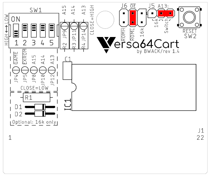
Properly configured Versa64Cart (for Diagnostic 586220)
The software does a couple of internal tests (like RAM tests). For the interface (external tests), some feed back connections are required. The Diagnostic will toggle the (outpout) pins on User Port, Cassette Port, the IEC (Serial) connections, the keyboard and the control ports and reads it back on other (input) pins. The harness provides the correct connections of the pins for those tests.
The Diagnostic Harness
There are different harnesses being sold or available as open hardware for you to build. The Diagnostic 586220 harnesses all provide the same of thos connections. They might look different.
The Diagnostic Harness, that I have designed is available on github. The design was made to be an easy build.
The Diagnostic Harness
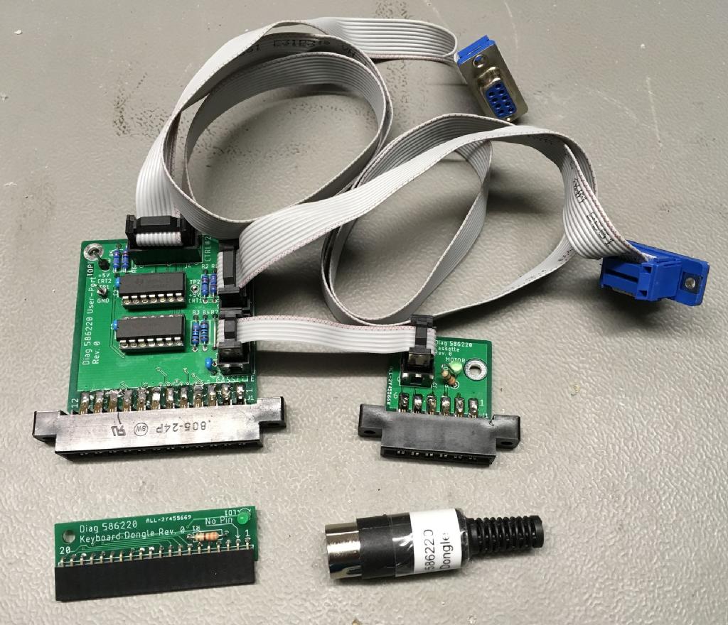
Beside the Diagnostic Cartridge, it consists of five main parts:
● The User Port PCB (click for schematics)
● The Cassette Port PCB
● The Keyboard PCB
● The IEC feedback connector
● The Cables
The User Port PCB provides the feedbacks for the User Port, the feedbacks for the Control Ports (=analog switches, controlled by the Cassette Motor signal ), fix resistors for POTX and POTY of both control ports and the feedbacks for the Cassette Port.
The Cassette Port PCB does not have any feedbacks (to make it more versatile), but it connects to the User Port PCB via a ribbon cable. The LED on the Cassette Port PCB indicates the status of the Motor signal. It will be one right after power up while the cassette port is tested and while the control ports are tested. Other than that, the LED is off.
The Keyboard PCB provides feedback for testing the keyboard and the LED works as an alternative power LED (the actual power LED might not be connected while testing).
The IEC feedback connector is just two wires in a 6-pin DIN connector.
The cables are all making use of ribbon cables and IDC connectors. IDC means "insulation displacement connector". The ribbon cables are inserted into the (still open) connector, which is then compressed (= closed). This does not require fancy tools, just a little wrench, which holds the connector and is closed carefully (until you hear the click, when the parts snap together).
A case for the user port and the cassette port PCB for 3D printing and labels are also available from the github repository. It serves as a protection for both assemblies. The User Port PCB is very sensitive to ESD. If no case is used, it should be stored in an ESD safe package.
Usage of the Diagnostic Harness
It is advised to read the Commodore "C64 Diagnostic Intruction And Troubleshooting Manual Assembly #326070-01" from 1992 before testing. The output of the complete test has to fit the C64 screen, so it is not very precise. A "BAD" does not mean, that the part is dead or damaged, it only shows a possible cause of failure.
The single tests are descibed in the manual mentioned before. This description can provide hints, when searching for the failure.
The fact, that the keyboard PCB is actually short circuiting the analog switches on the User Port PCB is not mentioned in this manual. Don't worry, nothing will be damaged, but the control port test could report a false "OK".
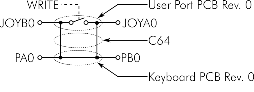
The analog switches on the UP PCB do not have any effect, while the Keyboard PCB is inserted
The picture above shows the situation while the keyboard PCB is inserted:
The Joysticks and the keyboard share the same port pins of CIA1 (U1). The (diagnostic) feedbacks for both are also the same, so it is not harmful to neither the harness nor the C64. But instead of testing the copper traces, the EMI filters and the Control Port connector, only the CIA pins and the short coper traces to the keyboard connector are tested (again). This can be proved by removing the analog switches (4066) from the User Port PCB. The control ports are still reported "OK". This observation was reported to me by Sinan Seyhun in January 2020.
The Harness can also be used for testing a C128, and the particular manual mentions, that the keyboard PCB should be removed for proper control port testing.
So, for properly testing your C64, you need to run two passes: one with and one without the keyboard PCB. Without it, the keyboard will be reported as "OPEN", which is not counted as a failure.
Revision 1
I am happy to announce, that for the first time in over 30 years, the Diagnostic Harness has advanced a bit.
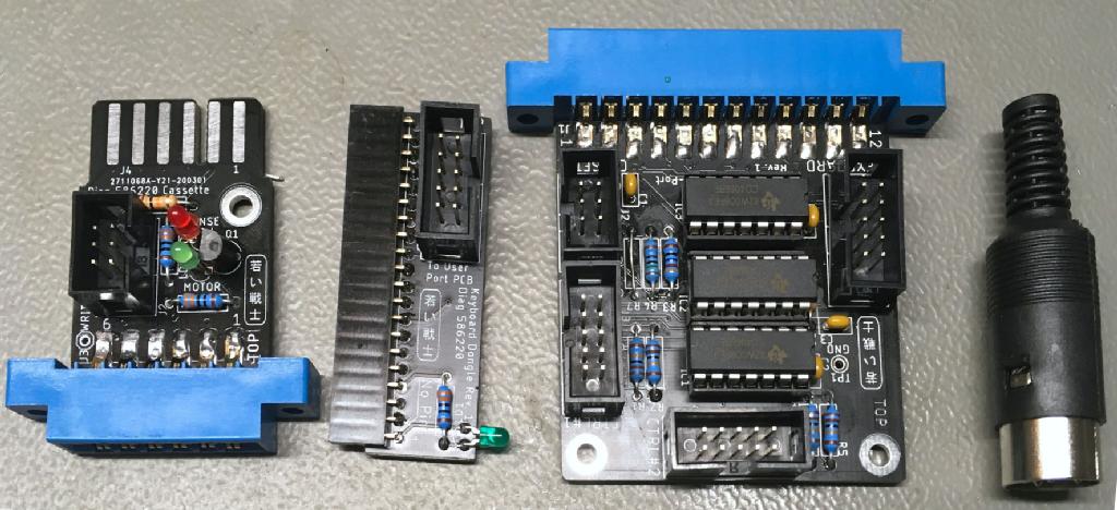
Diagnostic Harness Rev. 1 without cases
So, what has changed?
First of all, the feedbacks on the keyboard PCB (Rev. 1) are switched off while the Control Ports are tested. This is to ensure, that the signals from the CIA take the way via the control ports to the User Port PCB, where they are fed back. This requires a 4066 analog switch IC more on the latter PCB, also, there are now two connectors more (one one the User Port PCB, the other on the Keyboard PCB and a ribbon cable. All simple and cheap components. As a result, the C64 can be tested properly in one pass. And the good new is, that the same regulare software can be used.
The Cassette Port PCB is now more usefull. It has always been a break out board for the Cassette Port, but... now, there is a connector for the Datassette. This means, you can connect this PCB to your cassette Port and also to a Datassette. The signals can be measured at the (boxed) pin header. The User Port PCB must not be connected while this kind of use, since it contains the cassette port feedbacks. The state of the Motor and the Sense signal are indicated on an LED each.
Revision 2
Revision 2 adds an option for the SX-64, which does not have a cassette port. The cassette port is required to switch the analog switches, that are testing the control ports, though.
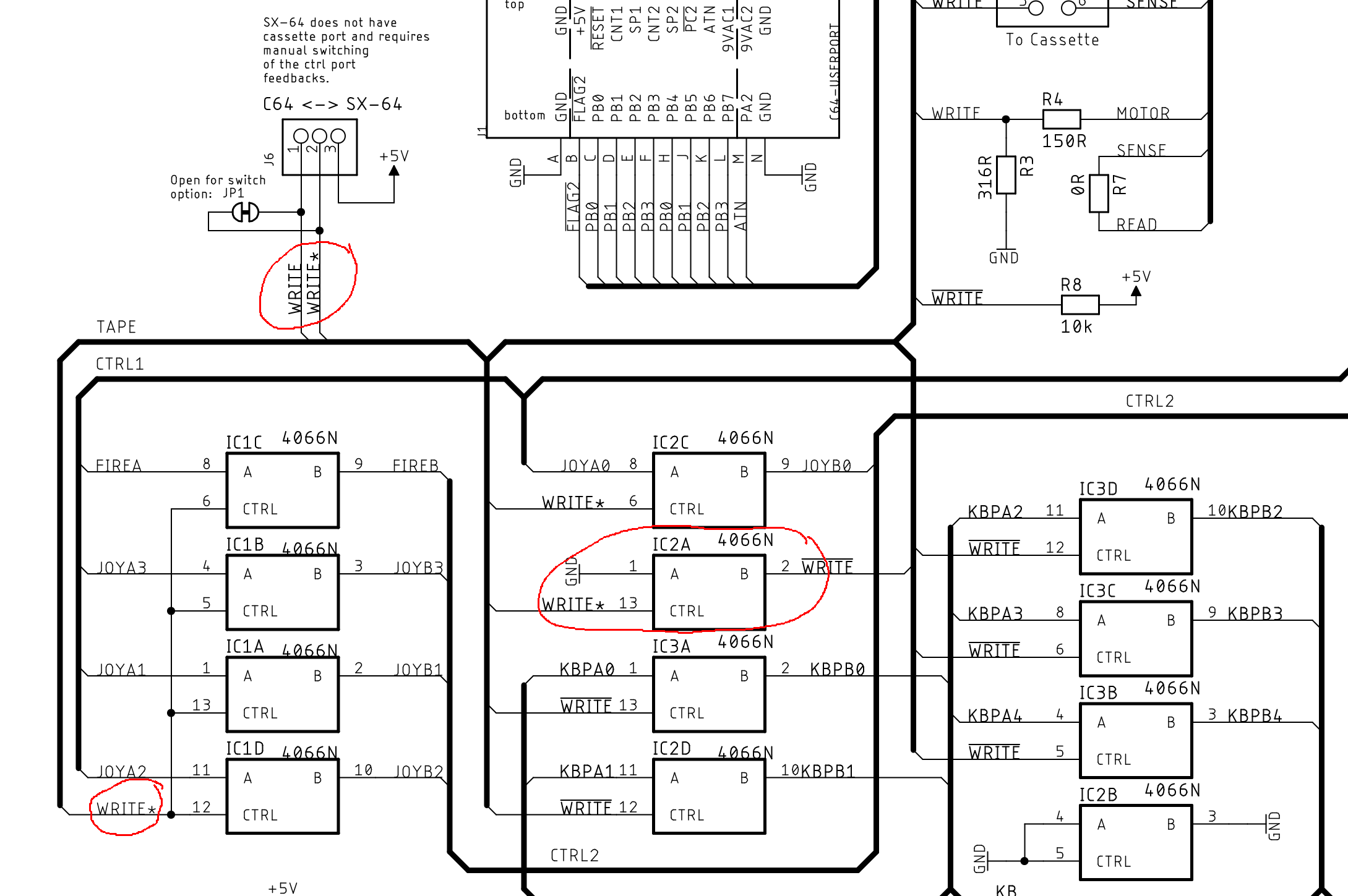
Excerpt from the user port dongle schematic rev. 2
The Extended Keyboard PCB
For existing diagnostic harnesses Rev. 0 or other harnesses, there is also a fix. The Extended Keybopard PCB. You don't need this board with Rev. 1 or later Harnesses.
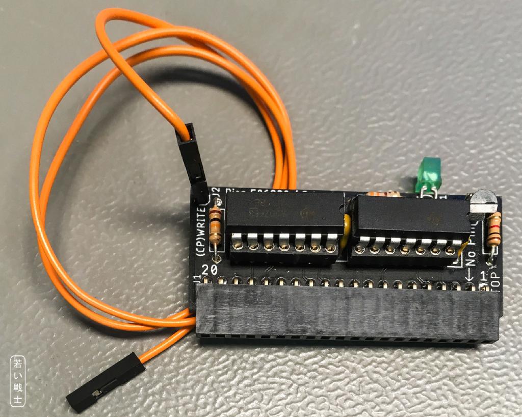
The Extended Keyboard PCB
The Extended Keyboard PCB is using analog switches to open the feedbacks, that are in common with the control ports, while the control ports are tested.
This requires a single cable to the Cassette Port PCB. It has to be connected to the WRITE signal of the Cassette Port (which is used to switch on the feedbacks for the comtrol port tests). This write Signal is inverted on the Extended Keyboard PCB and used to control the (4066) analog switches for the keyboard feed backs. So "Control Port feedbacks on" = "Keyboard feedbacks off" and vice versa.
In case the keyboard feedbacks are not switched, the diagnostic software will report the keyboard as "BAD" (not "OPEN" anymore), because three feedbacks are not shared with the control ports, so they are still fix, so not all feedbacks are open, which would be reported as "OPEN".
The Extended Keyboard Dongle can be used with "my" Diagnostic Harness Rev. 0 (Rev. 1 does not require it). It can also be used as with harnesses of other makes. It is only required to locate the WRITE signal.
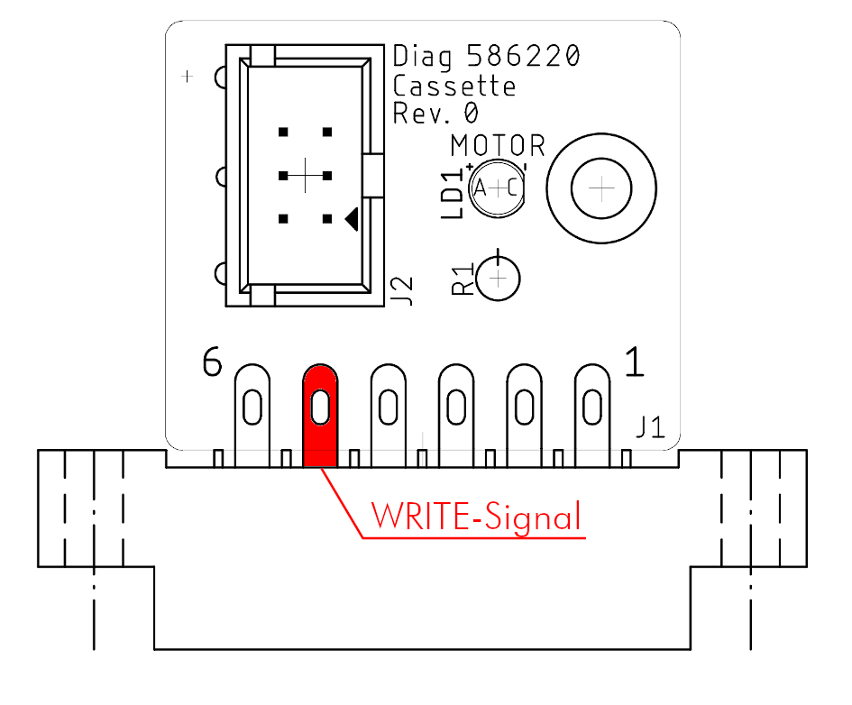
The location of the WRITE signal
The WRITE Signal can be found at pin 5 of the Cassette Port. A Dupont Wire (at least 30cm) can be soldered to this Pin. Since all Diagnostic 586220 harnesses work with the same principles, this applies to all such harnesses.
The Keyboard PCB for the C128
The Keyboard PCB for the C128 is optional. It provides the required feedbacks for the keyboard test of the C128 (with internal and external keyboard). It has thh identical 2x5 boxed connector like the C64 Keyboard PCB. The shared feedbacks are open while control port test.
One of the feedbacks (PA7 - PB7) is acting like a pressed run-stop key. This is causing the C128 booting to the ML monitor. The C128 Keyboadr PCB can open this feedback while the button "DISABLE RUN/STOP"is pressed. This should be one while switching on the C128.
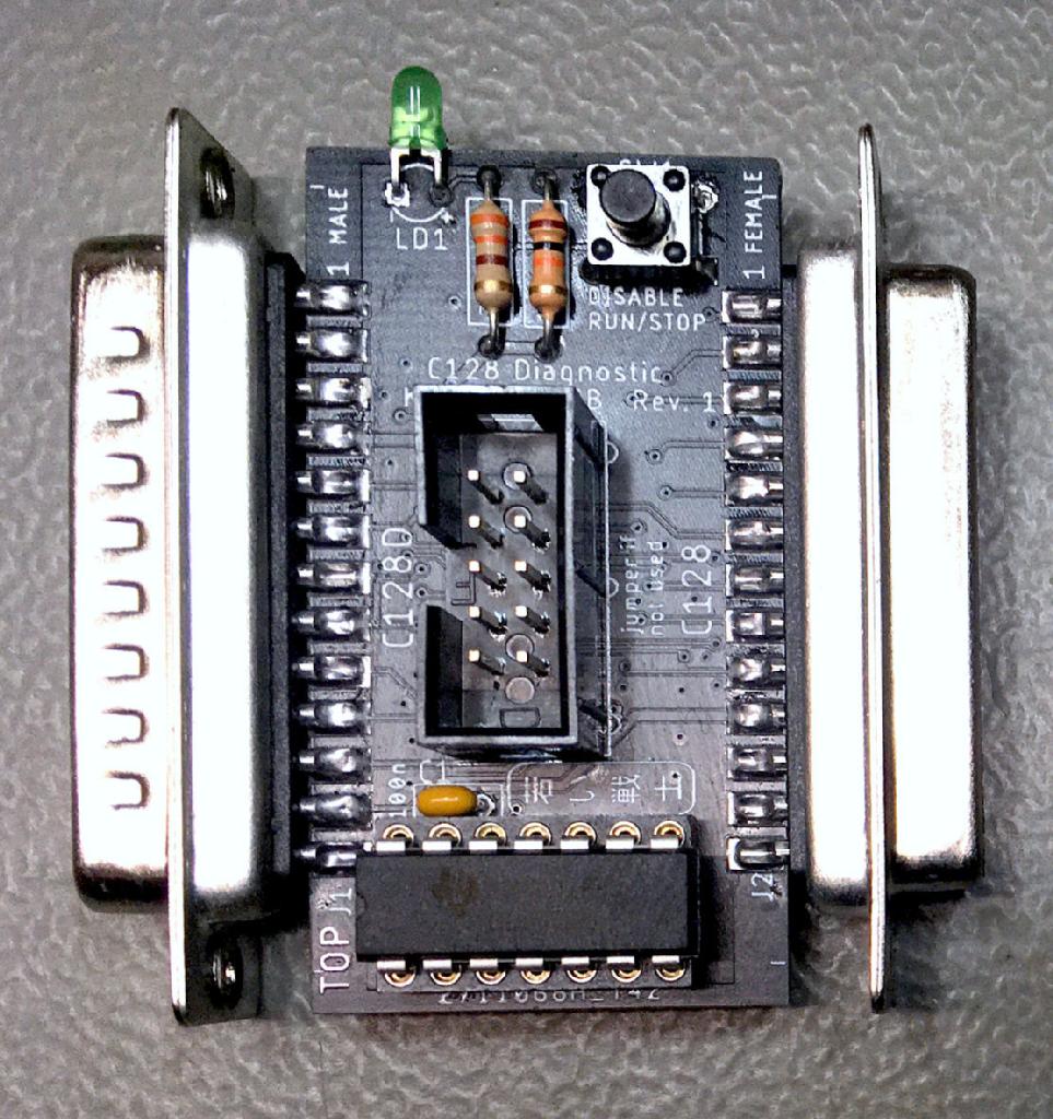
C128 Keyboard Dongle
The C128 Keyboard PCB has a 25 way male and female D-Sub connector. The male connector fits the C128D and the female connector fits the C128 keyboard pin header on the main board.
The box pin header on the C128 KB PCBN has to be jumpered in case it is not used with a User Port PCB Rev. 1 or any other harness.
This C128 KB PCB was developed on suggestion and tested with the help of Jeff Birt ("Hey Birt!" on Youtube). I do not own a C128.
Jeroen Vlasveld has tested the C128 Keyboard Dongle with the SX-64, using a 25 way female-female D-Sub gender changer. on an SX-64 keyboard cable.
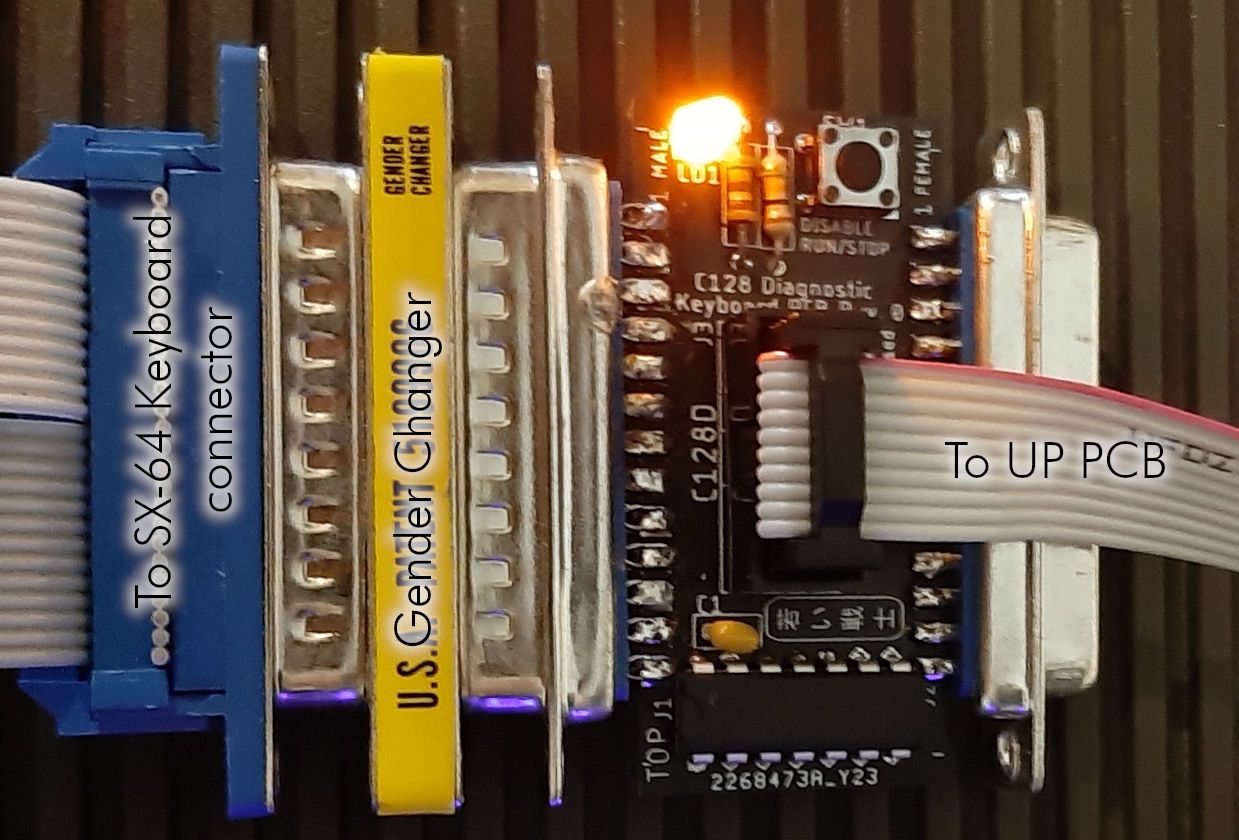
Testing the SX-64 with the C128 KB PCB
Thank you, Jeff and Jeroen for your help. Much appreciated!
Cables
The lengths od the cables defined for standard C64 and C64C. The C128s require longer cables. These lengths are noted in the cable drawings. Jeff Birt has provided the measures for the C128.
Three sorts of cables are required for the diagnostic harness:
● Cable from User Port PCB to Control Port (2x): Cable Drawing
● Cable from User Port PCB to Cassette PCB (1x): Cable Drawing
● Cable from User Port PCB to Keyboard PCB (C64 and C128) (1x): Cable Drawing