C64 Diagnostic and Dead Test Cartridge
Content
● Introduction
● Diagnostic cartridge based on a Versa64cart
● EPROM images
● Brief Software Description
● DIAG64cart
Introduction
The C64 Diagnostic Rev. 586220 Harness also requires an (EPROM) cartridge, that is holding the software. Personally, I like bwack's Versa64Cart for that purpose, SukkoPera's OpenC64Cart works as well.
Another way is to use the dedicated DIAG64cart.
The C64 Dead Test Rev. 781220 is another test software, which was originally issued by Commodore for testing the C64. It is a very basic test and an important part is the RAM test. A broken RAM will be indicated by the number of fashes of the black screen. Without RAM, there is no proper display possible.
Diagnostic cartridge based on a Versa64cart
Since both test software are essential in the C64 repair workshop, it would be good to combine both on a single cartridge. Switching both might be a good thing.
It is not a big deal to burn both *.bin files on an EPROM, but there are some more settings required.
The A13 bit of the EPROM offset address is a result of placing the Diagnostic software from $0000 to $1FFF and the Dead Test from $2000 to $3FFF. (those are hexadecimal numbers). A14 and A15 are both LOW (for a 27C512 EPROM).
The goal is to set up the cartridge with a simple DPDT (Double Pole Double Throw) switch:
● One pole of this switch can clearly be /OE switching between /ROML and /ROMH.
● GND can be switched to either /GAME and /EXROM, since only one is low at a time and there are pull-up resistors in the C64, holding them HIGH.
● A13 is identical to /EXROM
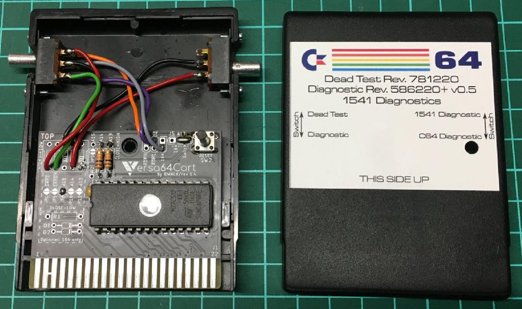
This can be done with a DPDT switch and a Versa64Cart:
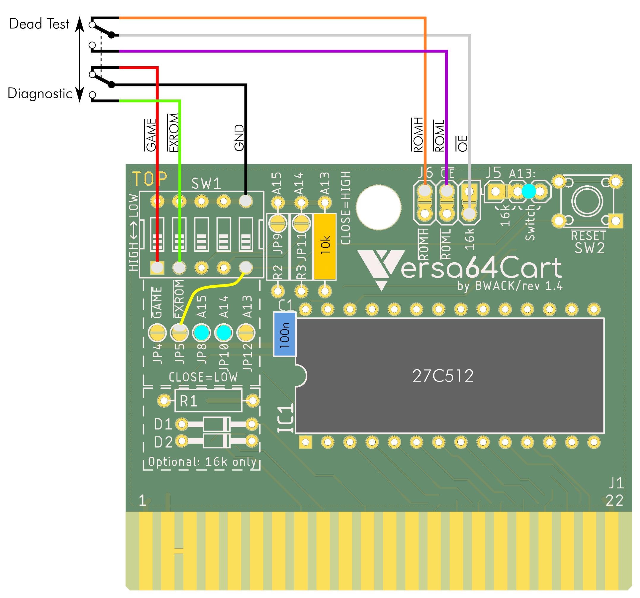
Wiring diagram of the DPDT switch, which is connected to the Versa64Cart (v1.4)
The most revent versions (v1.5 and v1.6) of the Versa64cart provide more soder pads for the DIP-Switch, which makes wiring even simpler.
Now, the 27C512 provides 64kB od programm space. That are eight 8kB blocks which is the regular size of a diagnostioc or dead test software, so why not programming more than only these two programs into this EPROM? It requires and additional switch for the address bit A14.
This can also be built with a Versa64cart.
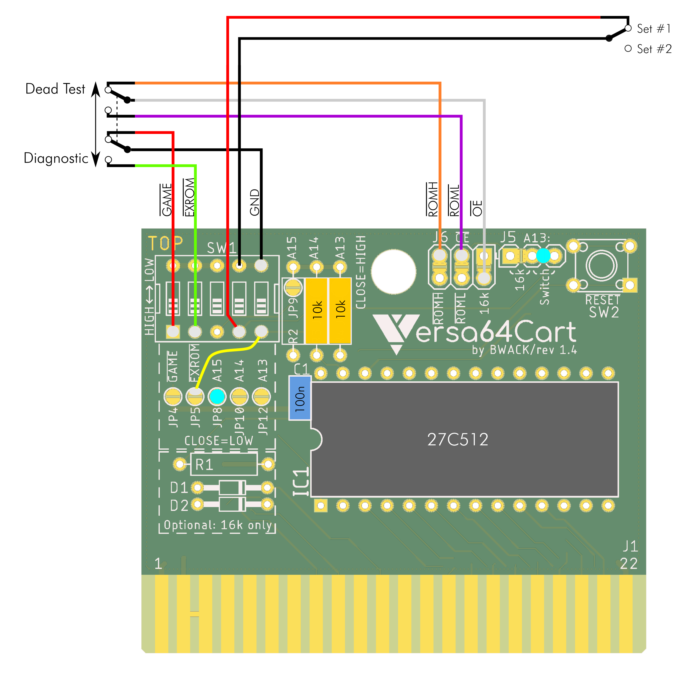
Wiring diagram of the "4xDiagnostic" cartridge
"Super Diagnostic" cartridge
The label was made prior to the discovery of the STID dead test. It might be a good idea to add a reset button to the Versa64Cart here. A TACT switch (6mm x 6mm) with a height of 9.5mm might be sufficient.
The Versa64Cart provides solder bridges for configuration, which results in a minimal requirement of parts. The schematic above shows this configuration for the 27C512 type EPROM:
● JP8 is bridged (= A15 is LOW)
● J5 is set to "Switch" (=/OE is in 8k mode)
For 27C256 type EPROMs, A15 has to be HIGH => JP8 is open and R2 is 10kOhm.
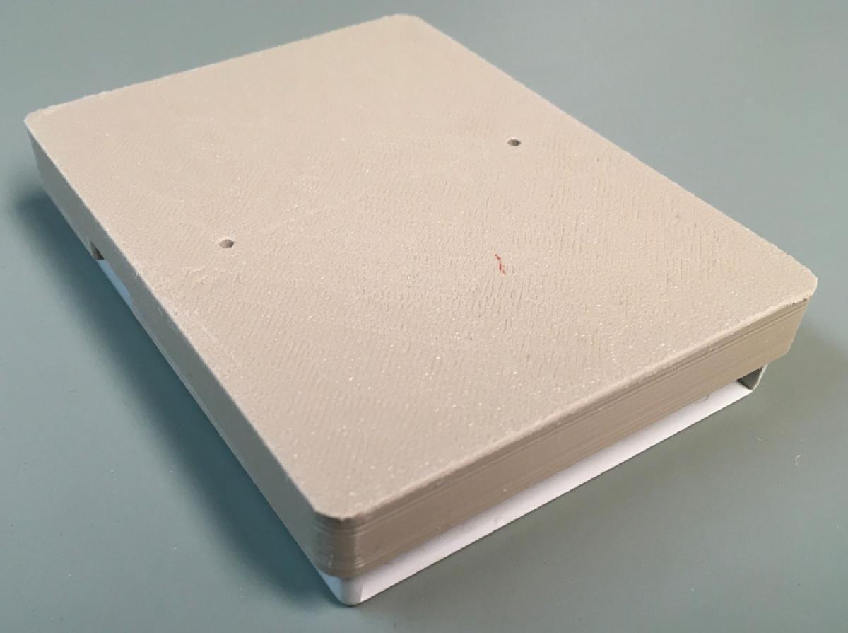
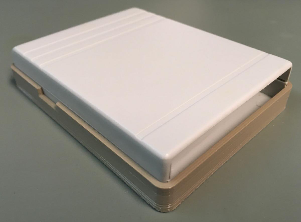
The cartridge case for the C64, which I have purchased from www.restore-store.de is pretty nice and slim. It provides the space for holding the switch. It does not allow a socket for the EPROM. Also, the Versa64Cart is a little bit to narrow, so I have created a 3D-print adapter, which holds the PCB centered.
All the cable soldering is no fun, so I have made the DIAG64cart.
The 3D printed Versa64cart Adapter can be found here: https://github.com/svenpetersen1965/Versa64cart-adapter_km20-z7
EPROM Images
The single binary files have been combined to one 32kb image, which you can download here.
The diagnostic software was obtained from World of Jani as well as the 1541 diagnostic software. The STID dead test was downloaded from Stefano Furiosi's github repository.
Diagnostic 4.1.1 is using the same diagnostic harness as the Diagnostic Rev. 586220, so it might be desired to replace the 1541 diagnostic (which I really, really like) with it in the EPROM image.
Brief Software Description
Diagnostic Rev. 586220 (the ++version recognizes several different kernals), it requires a diagnostic harness to properly test the interfaces.
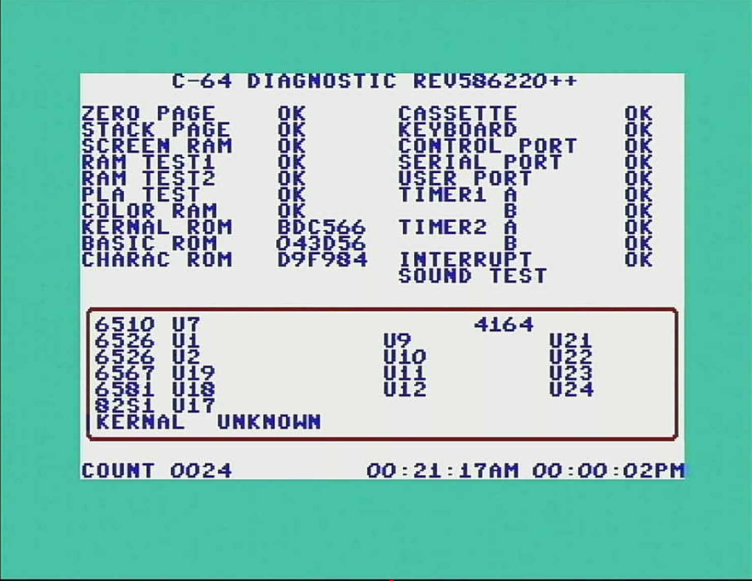
The Diagnostic Rev. 586220 without a harness reports several BAD interfaces/ICs:
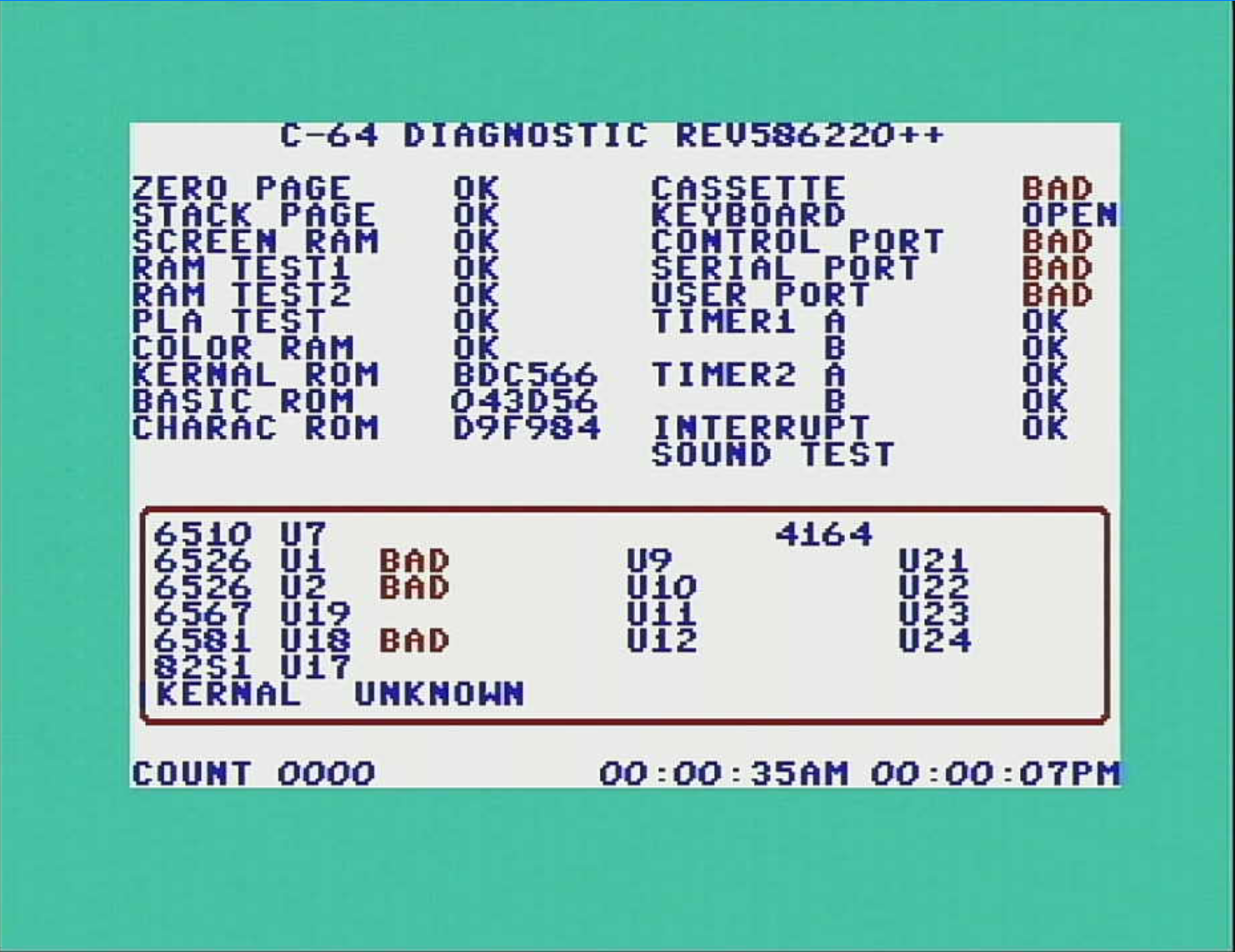
Note: It is advised to read the Diagnostic Manual before using the software. Not every component, that is reported BAD is broken. The software only suggests to check it.
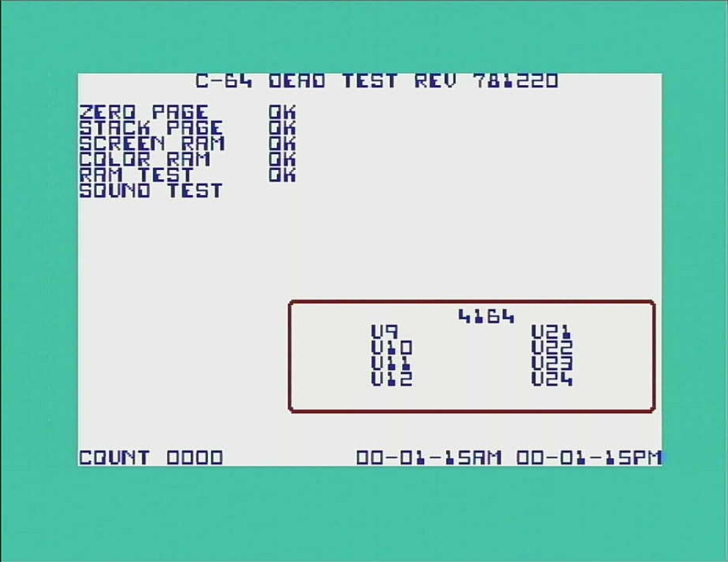
Dead Test Rev. 78120 works without ROMs (Kernal, BASIC and charachter generator) and the SID. It even signalizes broken RAM with screen flashes. It is recommended for a basic testing of even dead C64s. Note: The RAM test only tests the lowest 4k RAM, not all 64k. It is strictly required to read the dead test manual.
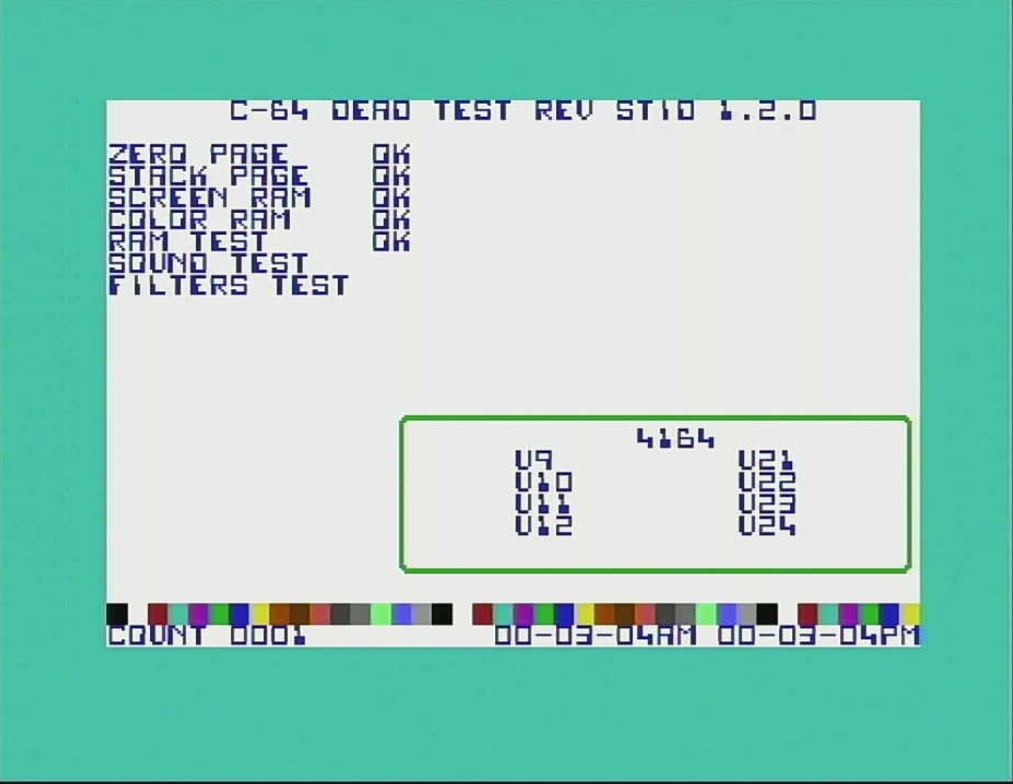
Dead Test STID 1.2.0 is an extended version of Dead Test Rev. 781220. It additionally changes the color of the screen border on each test loop, it shows a color bar and most important, it performs a filter test. The SID filter is sometimes dying secretly (which happens quite often) and it is not easy to find out without this "reference test".
Find a reference run of both Dead Tests on Youtube. (WARNING Do not click this link, if you don't want youtube do, whatever they do with your data/computer).
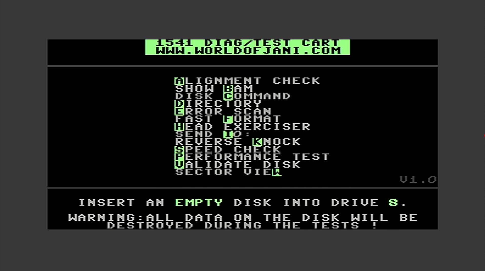
The 1541 diagnostics is a great utility to test and fix the 1541 (and 1541-II) floppy disk drive. I really recommend having it.
The DIAG64cart is derived from the Versa64cart and my previous work. It is designed to fit into the Maszczyk KM-20 or the Kradex Z-7 cartridge cases. The switches are soldered to the PCB and don't require any cables anymore.
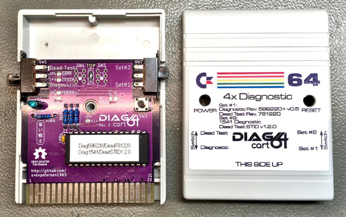
The DIAG64cart in a Maszczyk KM-20 case
The DIAG64cart is configured to fit the purpose of the 4x Diagnostic Cartridge, mentioned before. The Dead Test and Dioagnostic software has to be loaded to a certain memory slot, like shown in the table for the Super Diagnostic Cartridge. The switches select the memory slot and the required configuration of /GAME, /EXROM and /OE (chip select).
To add more flexibility to the cartridge there are solder bridges, which can be closed or opened to modify the default configuration.
E.G. the C128 works differently than the C64. If the C128 finds either /GAME or /EXROM LOW, it will boot into the C64 mode. For a C128 cartridge, both signals have to be high (=open).
The DIAG64cart is open hardware and can be found here: github
For "mass production" there is a jig for marking the switch cut outs (top and bottom) and the reset switch and power LED (top) on the Maszczyk KM-20 case.