


C64 PSU: PolyPower64
This is a still unreleased project.
It has shown, that PCB mount tzransformers are insanely expensive in North America, but chassis mount transformers are available for a half decent prices (still more expensive than in Europe).
This is, why Mark Tocheri (MindFlareRetro) asked me for co-operation.
It has shown, that PCB mount tzransformers are insanely expensive in North America, but chassis mount transformers are available for a half decent prices (still more expensive than in Europe).
This is, why Mark Tocheri (MindFlareRetro) asked me for co-operation.
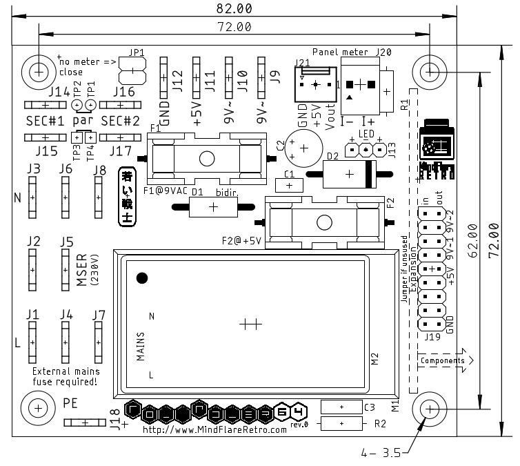
PolyPower64 drawing and dimensions
I have to admit, that this project suffers a bit from procrastination.
Anyways, it is the mother of two other of my power supply projects, since some ideas were developed for the PolyPower64, that then have been part of the C64 PSU global and C64 CPU combi.
That is the expansion module, which might be used for measurement/display or monitoring purposes. and the switchability between 230V and 115V (120V).
Transformer configuration for a mains voltage of 115V and for 230V
The switchable transformers have two primary windings, which asre connected in parallel for 115V and in series for 230V. Since some of those transformers have two secondary 9V windings, those can be connected in parallel, too (or in series for 18VAC, which is not required in this project).
PCB and transformer
I did not plan to build a prototype myself, but finally, finally... I have ordered the PCB and the transformer from Mouser (a Triad VPT18-1390).
And a bit later, the prototypes have been assembled, too.
And a bit later, the prototypes have been assembled, too.
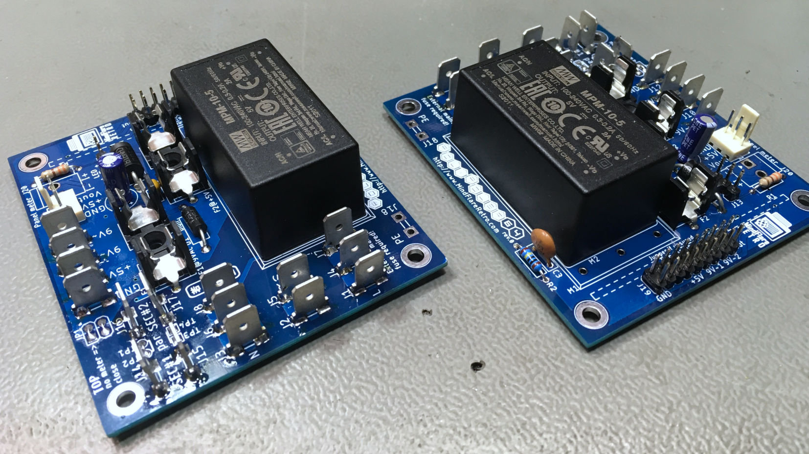
Two PolyPower64 Prototypes
The prototypes still require testing and case making.
The current measurement has already proved to be nonsense. I did not find any panelmeters, that are accurate enough for current measument. (the other problem with those panel meters is, they measure the current in the ground lead, which is nonsense, but since there is only one DC output voltage, it would be ok-ish).
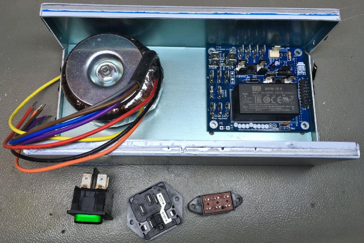
The case making has beguin... test fitting the components in a Teko 334.18 case
I had a couple of ideas, how a case could look like. I considered the transformer sitting under the PCB to get a very compact, almost cubical PSU. But... the transformer is the component that will be the hottest, so I refused this idea. Finally, I have desided to install the power supply in a >Teko 334.18 case, which is pretty wide, but not deep.
The cables are always kind of underestimated,. The FastOn connectors have a certain length, so the mains related components have to be placed in a way, that there is enough space for those connectors. Also, I want to have a switchable mains voltage (115V and 230V). The illuminated switch on the back side does not make much sense especially, because the illumination is pretty dim at 115V, but I had it in my project box.
I have drawn the cutouts on the backlpanel and printed it out. Then I placed the paper on the back side of the case and marked the corners of the rectangular cut outs and punched the center of the drills.
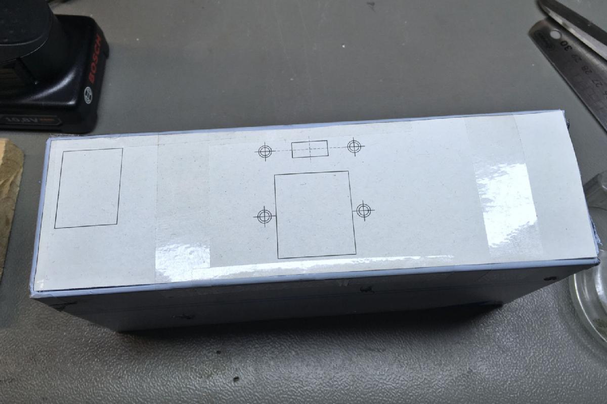
The printed backpannel serves for marking the cutouts and drills
After drawing the lines between the marks with a steel ruler, I drilled the holes and cut out the rectangels with a jig saw. I tried to leave enoug of the case, so I could file the cutouts to the exact measure.
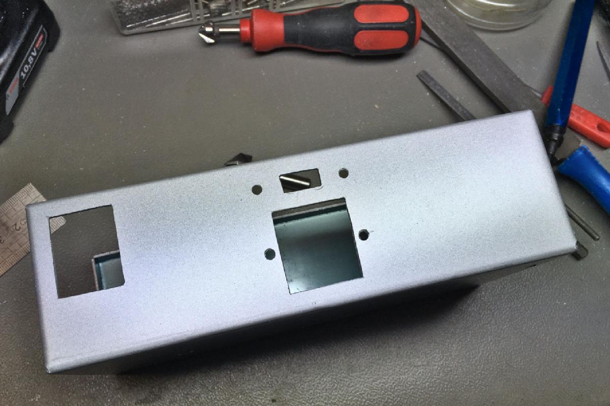
Back panel with all cutouts
The front panel has just two round holes.: one for the Power LED, the other for the cable strain relief. Those were done easily. And after cleaning the case from the metal chips with a vaccuum cleaner, the PCB and the other components could be installed.
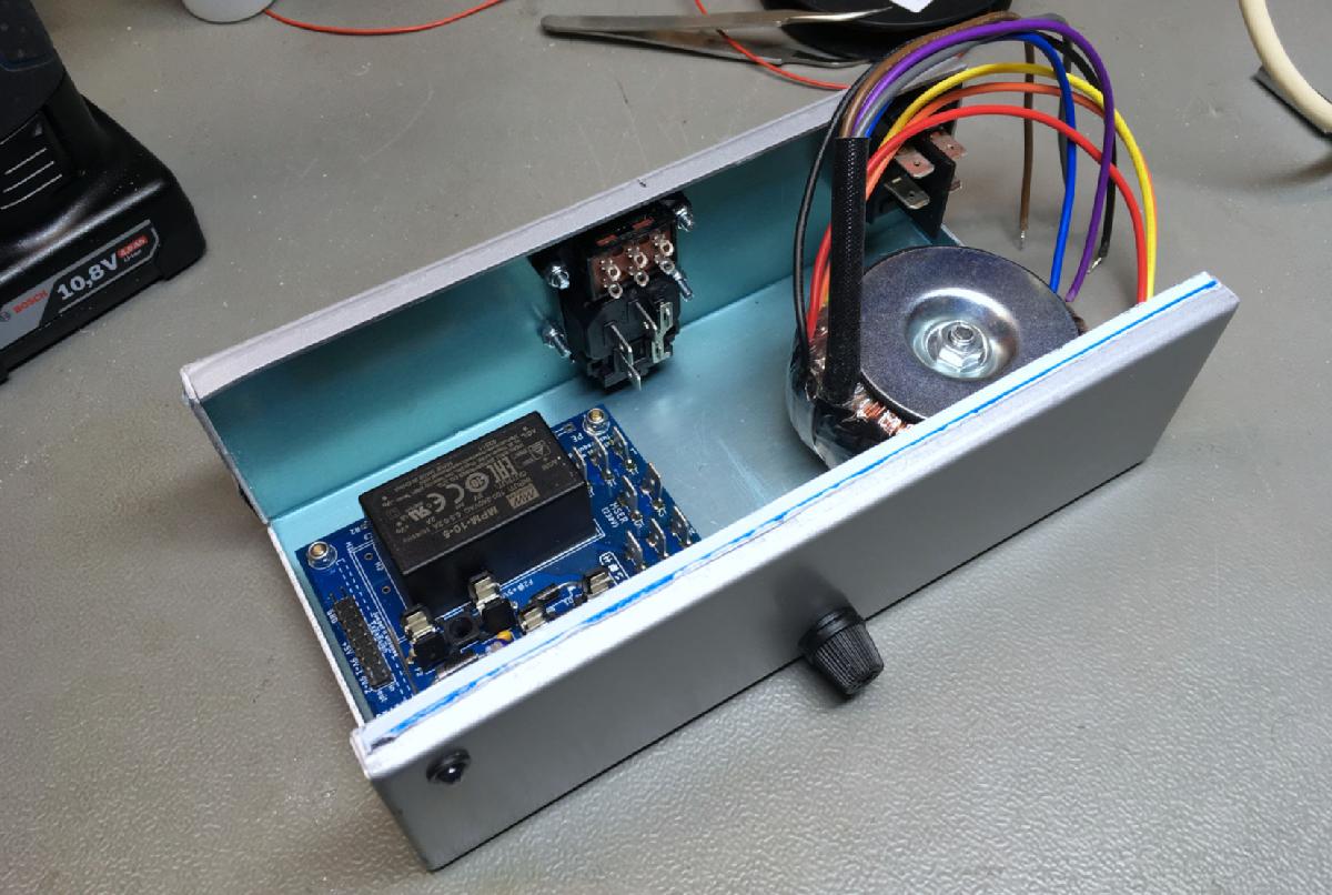
The case with the mounted components
To get a bit more space, I have moved the transformer to the back panel of the case, between the switch and the mains input.
As I have mentioned before, I want the PolyPower64 to be configurable as 115V and 230V device. The AC/DC converter has a wide range input and does both voltages. The transformer can be configured for both voltages, as shown in the sheet that came with it.
For 115VAC mains, bothe primary windings ahve to be in parallel (not in anti-parallel, the orientation is important!) and blue & violett have to be connected to N(eutral) and grey & brown have to be connected to L(ive).

Wiring of the mains voltage selection switch (optional)
For 230VAC mains, both primary windings are in series, which means blue is connected to N, brown is connected to L and grey & violet as connected to each other.
The mains voltage selection switch is optional. The transformer can be connected directly to the PCB for a fix configuration.
For 9VAC, both seconary outputs can be in parallel to get the maximum output power. That is 2.78A, which is quite a lot with the Triad VPT18-1390. Good enough to power a two-prong VIC-20 from it, BTW. It might be better, to switch off one secondary winding to get an output current rated 1.39A. The reason for a reduced output power is a higher voltage drop at the load of one C64. This way, the 5V linear regulator (7805) inside the C64 has to dissipate less power and will stay cooler. The sheet mentioned before says, the secondary black and orange are connected as well as red to yellow.
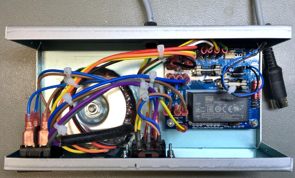
Preliminary wiring
The previous picture shows a preliminary wiring. I decided to try out a "precision panel meter" from Ali Express for the 5V. If this works out, I will install it.
The first test of the 5VDC was with an electronic load, I can test the 9VAC with load resistors, only, since the electronic load is only capable of DC.
The first test of the 5VDC was with an electronic load, I can test the 9VAC with load resistors, only, since the electronic load is only capable of DC.
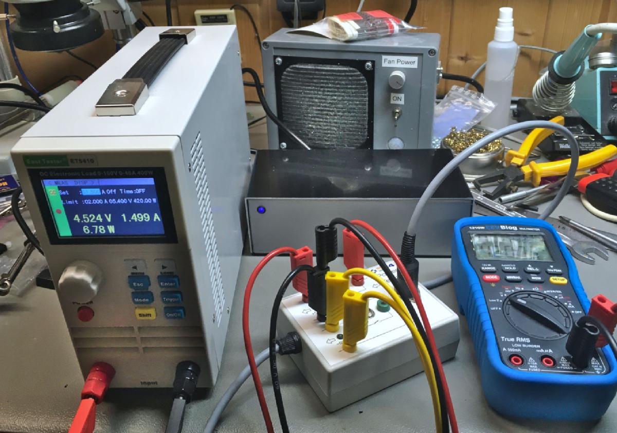
Testing with the electronic load
The PolyPower64 has an option for a panel meter. In general, I don't really like them,, because the current measurement is in the GND path (only one voltage can be measured, which is ok for a C64/VIC-20, because there is 5V only, the 9V are not measured).
I have once bought "am ordinary panel meter" for voltage and current, but they turned out to be completely off (like 40%) even after trying an adjustment - I could not set it lower) . That is no real information and not woth the air they displayce.
I have once bought "am ordinary panel meter" for voltage and current, but they turned out to be completely off (like 40%) even after trying an adjustment - I could not set it lower) . That is no real information and not woth the air they displayce.
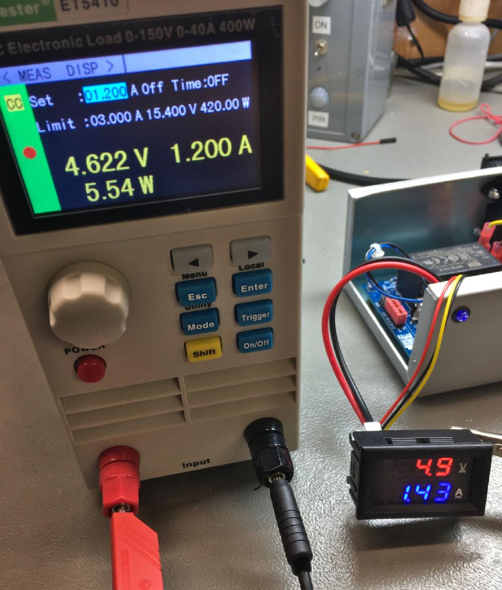
This is a bad panel meter! It ready 1.43A instead of 1.20A
The difference of the voltage readings of the electronic load and the panel meter is normal, because the panel meter measures inside and the electronic load at the end of long cables and connectors, which have some voltage drop at 1.2A.
But today, I have received an panel meter from Ali Express ("4 Digits High Precision DC 100V 200V 10A Voltmeter Ammeter Dual LED Digital Display Amp Volt Merter Panel Gauge"). I did not expect any good, but... I was wrong. The reading is precise enough for the purpose.
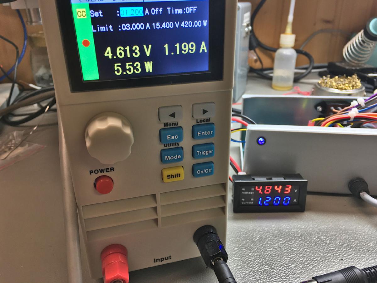
The good panel meter
Without a load, I could adjust the voltage pretty well. No load means no voltage drop over the cable.
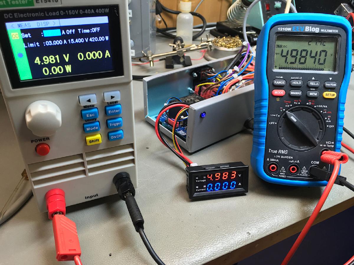
Panel meter with adjusted voltage and no load
The reading of all three instruments are pretty close. I noticed, that the resolution of the current reading is >10mV.
[... to be continued...]