


C64 PSU GLOBAL
Introduction
In case you wonder, why a new power supply for the C64 is required and it might be better not to use the old (original) power supply, ready about this topic here.
The C64 PSU Global had actually two or three main goals:
It should...
● be cheaper than my first C64 power supply
● be possible to use with mains voltages both 115VAC (120VAC) and 230VAC (240VAC).
● be possible to install a saver circuit in it
● have a 3D printed case
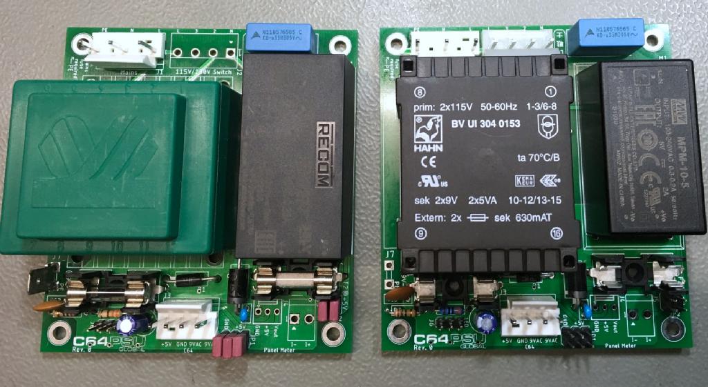
The 230VAC version (left) and the 230VAC/115VAC version (right)
The main components of this power supply are a transformer for the 9VAC and an AC/DC module for the +5VDC. For both of these components, two different footprints are possible:
● For the transformer, a 230V only model and a 115V/230V model
● For the AC/DC module, there is a RECOM (M1) and a Mean Well (M2) model that fit.
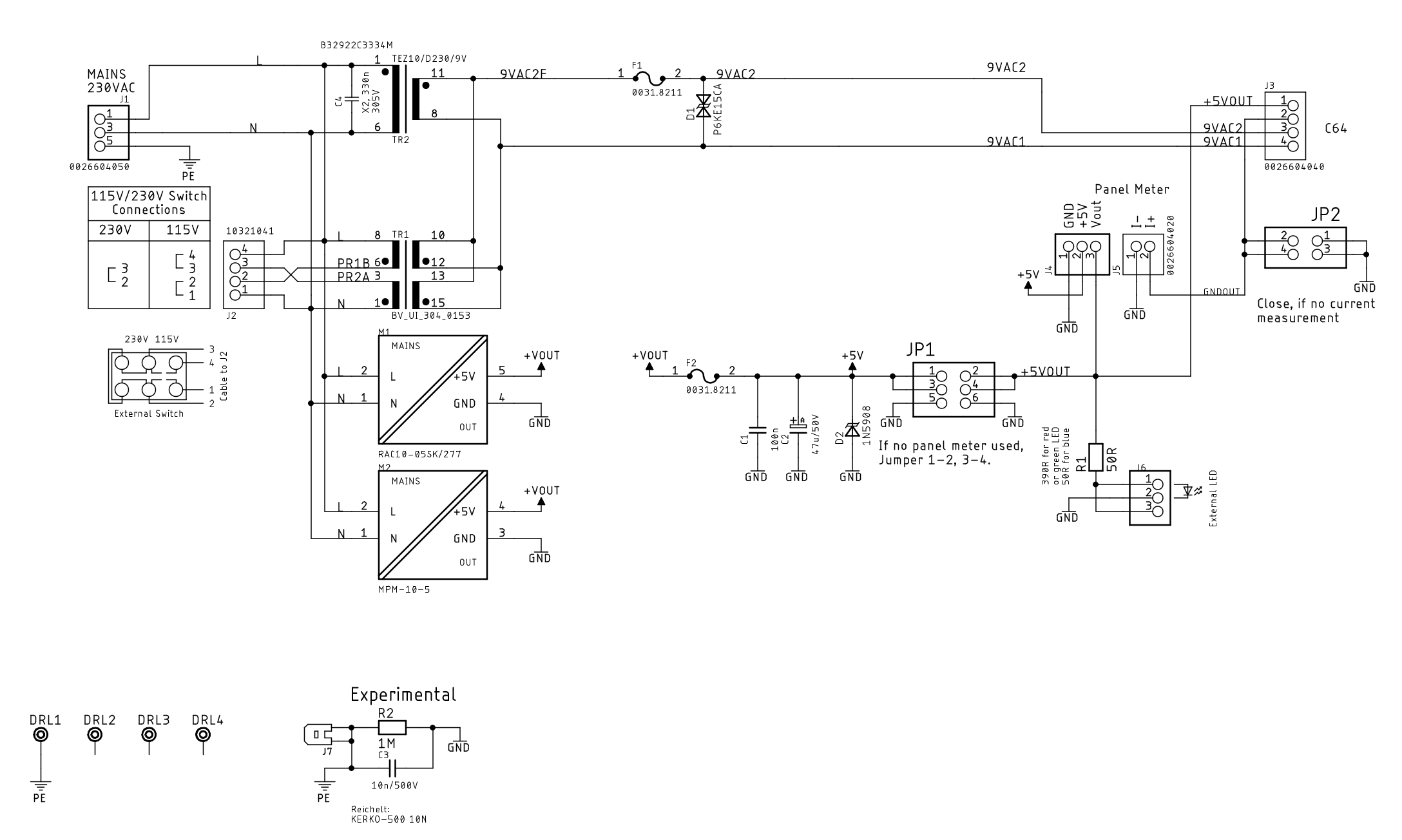
Schematic of the C64 PSU Global
The 115V/230V transformer (TR1) is sightly more expensive than the 230V only model (TR2). Also, it requires an addidional voltage selection switch and a connector (for that switch) to have the first version. TR1 has two primary and two secondary windings. For the required 9VAC, the secondary windings have to be connected in parallel to provide the full wattage (10VA). The primary windings are connected in parallel for 115V and in series for 230VAC mains voltage. The orientation of the windings must not be confused.
The AC/DC modules M1 and M2 are interchangable, both have a wide rance input and work for 115V and 230V (actually from 85VAC to 264VAC).
For the saver, which has yet to be developed, a 6 way pin header (JP1) provides GND, +5V (input) and +5V (output). in case the saver is not connected, the +5V (input to output) have to be bridged with jumpers.
The R2/C3 combination ties GND to PE (protective earth). This is of advantage, if there are other (cheap) power supplies or phone chargers are used for powering a Pi1541 and/or a S-Video/HDMI converter. Those tend to have a capacitive coupling between the mains and the (actually isolated) output voltage. This would inject (a very weak) mains voltage into the system. Touching the usper port or cassette port will create a noticeable flicker on the skin. This is not dangerous for the person, but might not be the most healthy thing you want to do to yout old CIA chips. The C64 PSU Global eliminates this effect.
The design is also pretty much straigt forward: a transformer for the 9VAC, an AC/DC converter for the +5V, both are fused. Some sources recommend the installation of suppressor (TVS) diodes as a (very basic) over-voltage protection. These are included in the design already. J4 and J5 are for connecting a Volt/Ampere panel meter (read below).
The pcb layout was a bit tricky around the mains connector. A certain distance is required between N(eutral), L(ife) and P(rotective)E(arth). To provide this, a five way 3.96mm (Molex) SPOX connector (J1) was selected for connecting mains, the 2nd and the 4th pin is pulled out of the connector. Also the connector for the mains voltage selector switch had to fit this requirement. For the four connection pins, a 7 was connector (with every 2nd pin pulled) would be required, unfortunately there is no 7 way SPOX connector. Since the voltage between adjacent pins is <= 115V, a shorter distance is viable so a 5.08mm SPOX connector was chosen. This eliminates swapping the output cable and the mains selector switch as well.
The Case
The case was constructed in Fusion 360. Since the 230VAC only version does not require a mains voltage selection switch, there have to be two versions of the case, which differ in the bottom shell.
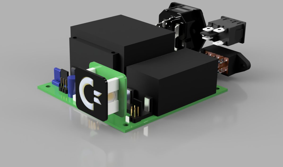
Before constructing the actual case, the components had to be arranged to determin the required dimensions.
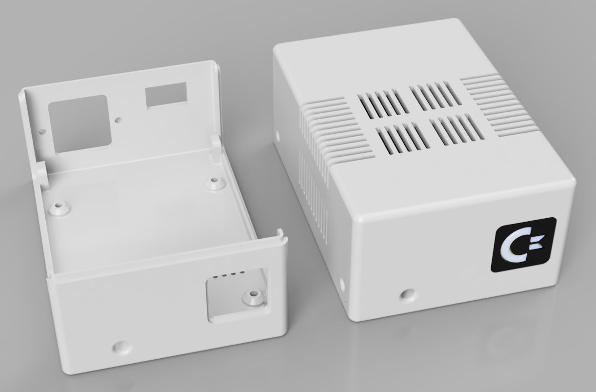
The 230V only bottom shell and the complete case (Fusion 360 rendering)
The construction is completely parametrised, so height, width and length can be changed to meet the individual requirements.
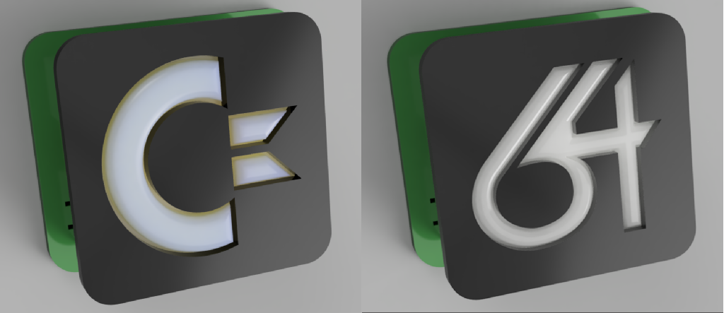
Two versions of an illuminated logo
There are two versions of illuminated logos: The Commodore logo and the 64 logo. The commodore logo is most probably still copyrighted, while the 64 logo might be not (I don't garantee for that). The logo(s) consist of a face plate, which can be glued into the bottom shell, an illuminated body (which is printed with transparent filament @ 100% infill), a white reflector, which increases the luminositiy significantly and a PCB whic serves as an an interconnect, that holds two LEDs with their current limiting resistors. The two LEDs are in parallel to allow blue and white LEDs.
Maybe there should be a simple face plate with just a power LED.
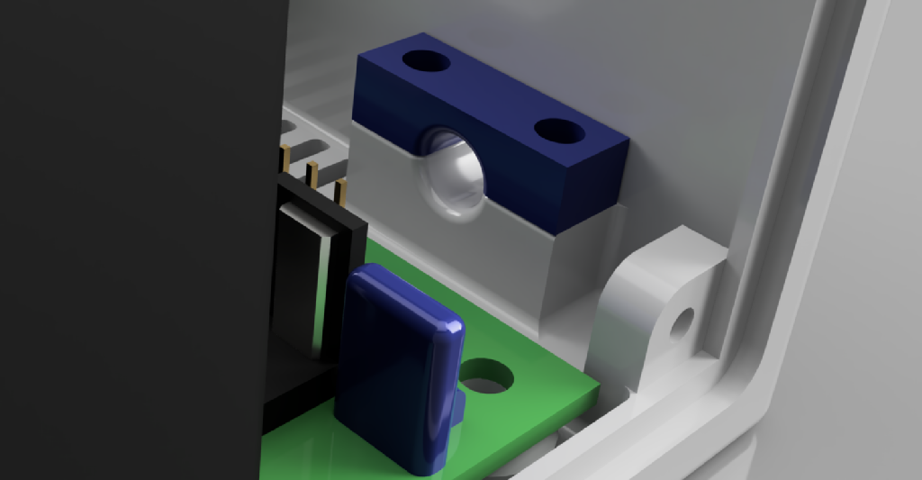
Strain relief (Fusion 360 rendering)
The strain relief is pretty much the same like in my joystick project. This has proved to work pretty well. The output cable fits through the hole in the front (5.5mm) pretty well, even with the crimp terminals for the PCB connector already attached. Since the bottom shell was replaced while testing (see below), I had to un- and re-install the cable a few times.
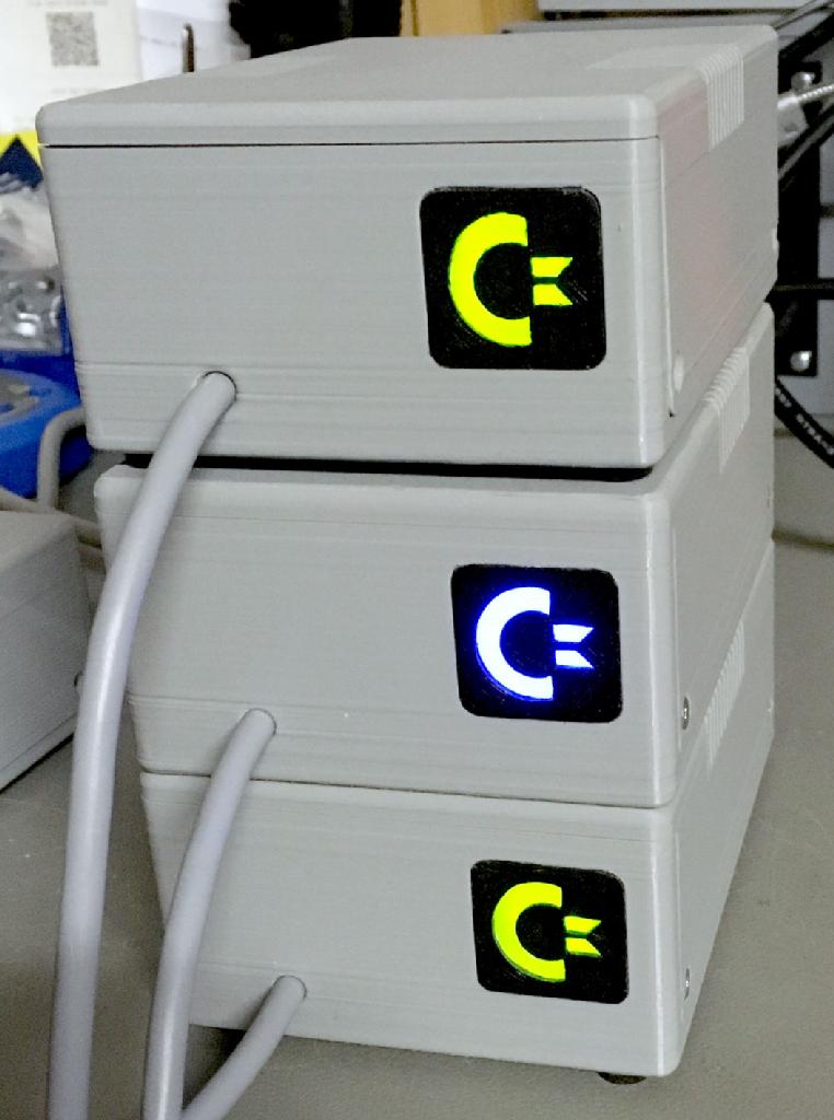
Three PSUs with the original case design.
Generally, it is possible to install the PCB in a metal case. It provides a grounding point (PE) and also a spade connector for grounding the top half of a metal case.
Originally, there is an option for connecting a volt/ampere panel meter for the 5Volts. This option is dropped due to a complete lack of accuracy of the current measurement.
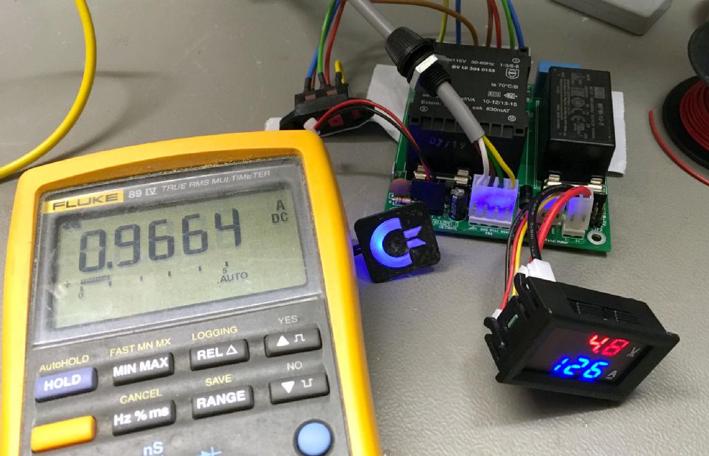
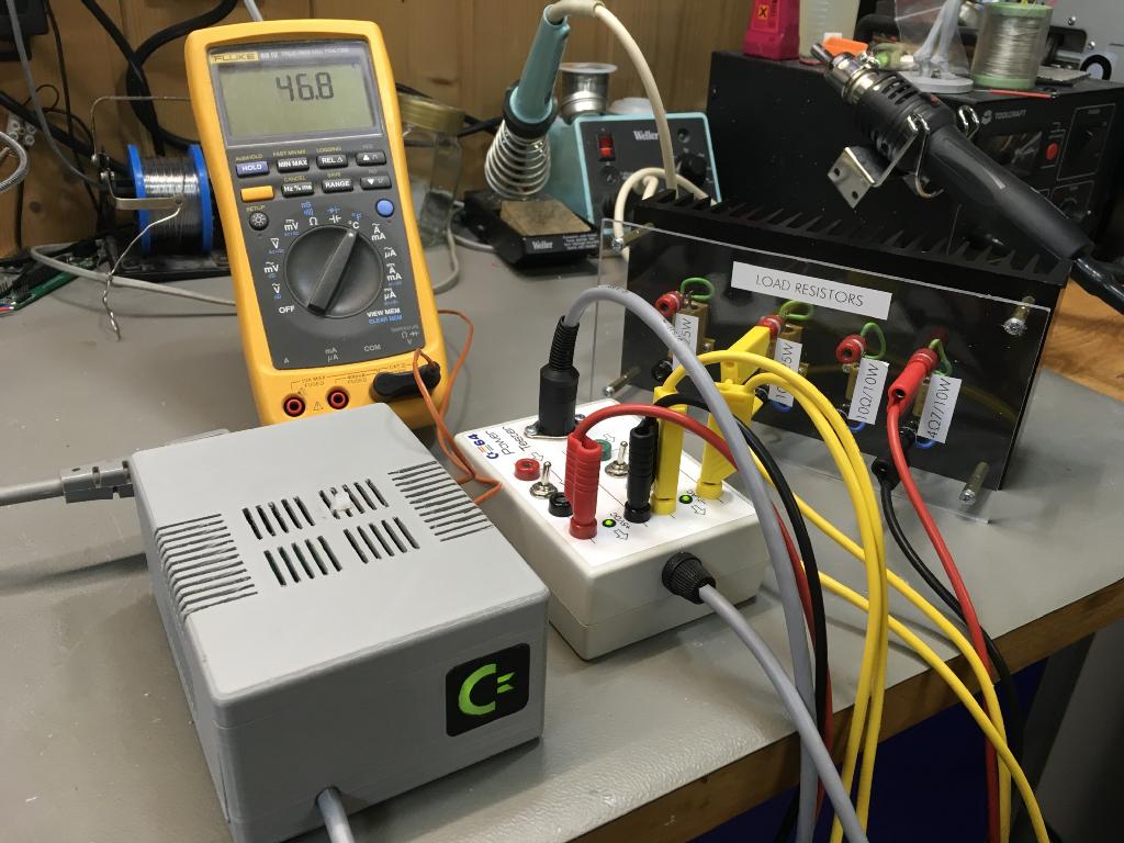
Comparison of the current value, with a multimeter and a panel meter
The originally adjusted panelmeter displayed a measure for the current, that was about 50% off. There are potentiometers for adjusting the voltage and current display, which worked fine for the voltage, but after adjustment, the current was still 30% off and could not be adjusted better. The multimeter showed 0.97A, the panelmeter 1.26A, which is 30% too high. I have also tried a 2nd panel meter from a different supplier. It has also been a slightly different model. It was even worse! In a future version of the PCB, the current measurement will be completely dropped. A voltage measurement will still be available, for those, who desire it. The panelmeter is not integrated in the 3D printed case.
Testing
The testing turned out to be major part of this development. Both versions of the power supply were tested successfully with
● ASSY 250407
● ASSY 250425
● ASSY 250466
● ASSY 250469
All those versions of the C64 were connected to an Ultimate II+ (Floppy Disk and everything emulator) and a Joystick Port Switch/Rapid fire and worked properly for at least two hours.
There was a noticable voltage drop after the AC/DC module, which outputs pretty much exactly 5V. This is to be further investigated (as of Feb. 12, 2020) and will be optimized in a further version of the PCB.
To prove, that the voltage selector switch was wired correctly, the PSU was tested with 115V. For this purpose an adjustable isolation transformer was used.
Isolation transformer for testing the 115V mains voltage mode.
The result is, the mains voltage selector and the transformer configuration work fine. The illuminated mains switch is pretty dim, though. At least for the 230V/115V model, a mains switch without a lamp is as good.
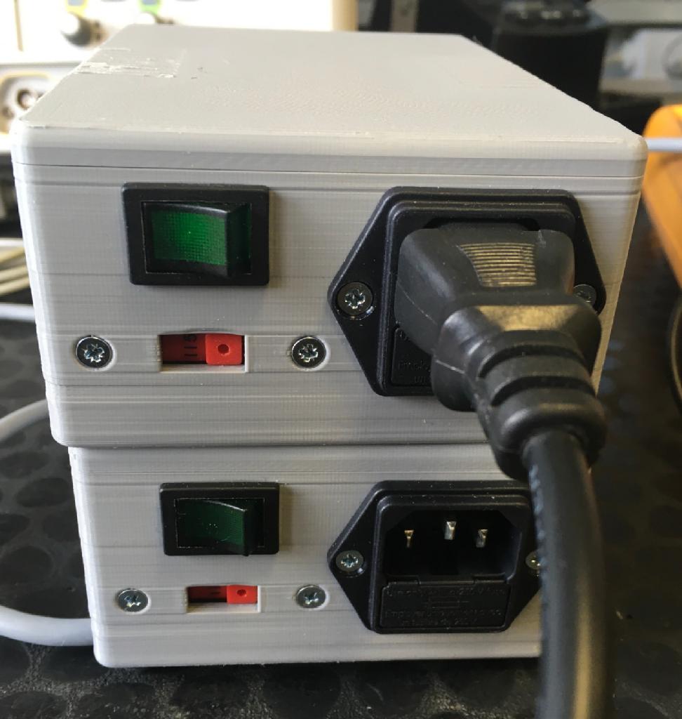
Dim Mains switch (top) at 115VAC
The temperature testing is a vital part of the procedure. Since the PLA filament (for 3D printing the case) has a critical temperature between 55°C and 60°C, it is desired to stay as far below as possible. Certainly, it is possible to print the case from a filament with a higher critical temperature, but PLA is the most popular material.
Setup of the temperature test
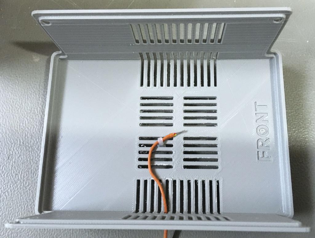
Location of the thermo couple while the test
Since about 50°C was reached with the original version of the case, this was finally made 4mm higher and received vetilation slots in the bottom shell and many more ventilation slots in the top shell. Load for the PSU was a 10Ohm resistor for the 9VAC and a 4.7Ohm resistor for the +5VDC. The temperature difference after the case modifications was about 1°C, which is much less than expected.
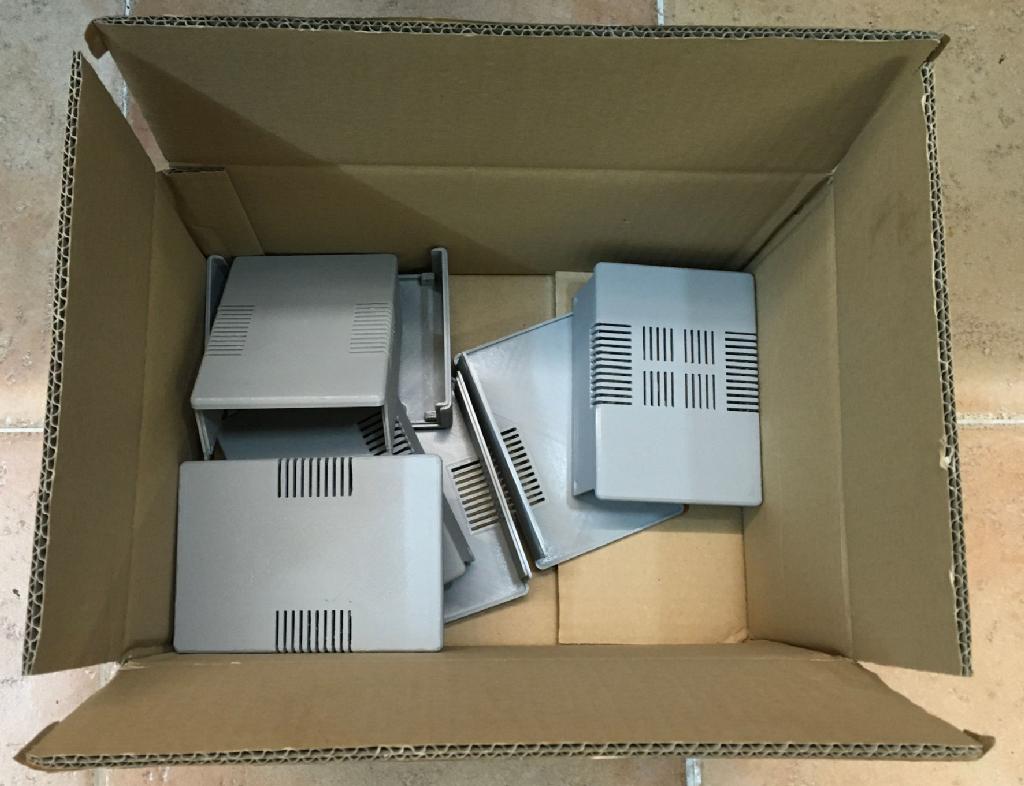
Dismissed 3D printed case parts
The complete case is worth about 130g of filament and a total printing time of about 14 hours. So there is a lot of material and time "wasted" in a box for later disposal.
The transformer was the warmest component of the PCB. At the end of the test, it had reached 60°C on its surface. The rated ambient temperature for the transformer is 70°C, so no probem here. The Mean Well AC/DC module is rated for up to 85°C ambient temperature, the RECOM module for 80°C).
After a two hours test like described, the (outer) top of the case is not more than luke warm and there is also no smell (PLA is generally not very smelly). An option would be an actuve cooling (fan), which is not desired. So a "real life" test was also conducted with an ASSY250407 C64 (an Ultimate II+ and Joystick port switcher is connected). After 8 hours a temperature between 43°C and 44°C was reached. This is far enough below the 55°C and about 20°C above room temperature (which was 24°C).
The result of the temperature tests is an "ok, but". The "but" means... an average real life C64 setup will work. The temperatures will stay in the "good" range as long as the room temperature does not exceed 30°C. In doubt, the case should be printed from PETG or a material that can take a higher temperature than PLA. A high additional load on the 9VAC, such as the Promenade EPROM programmer should not stay connected over hours.
I will keep my PLA case, since it works for me.
Anyways, this is a hobby project, provided as is and building and usage is on own risk. I will not be liable for any damages.
The C64 PSU Global is still a project in process. The original PCB works, there will be a further version without the panel meter, though. The case will be published a bit later and the testing has to be finished and documented.
Find this project on my github. The C= logo can be found here.