


C64 PSU Combi
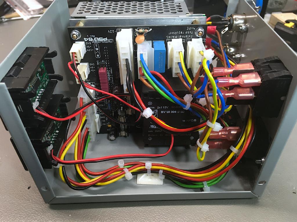
The C64 PSU Combi does not only power a C64, but also up to two 1541-II floppy disk drives. It is pretty handy and saves outlets. The 9VAC voltage is generated with a transformer. The DC voltages (+5V and +12V) are generated by a low priced DC power supply (Mean Well RD-50B).
0
0
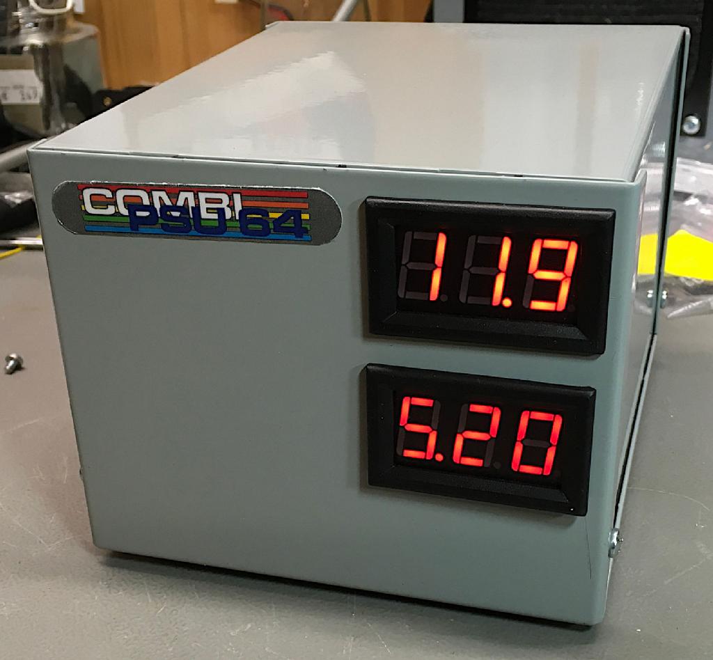
The front of the C64 PSU combi in a Hammond 1411P case
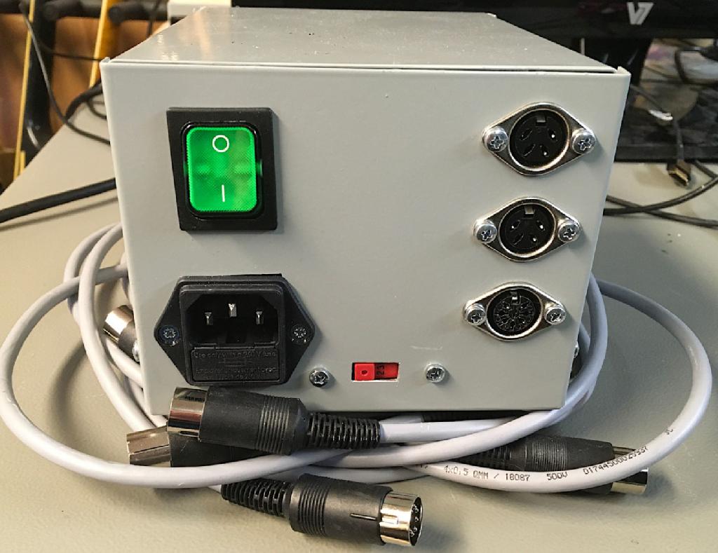
Back panel of the C64 PSU combi and detachable output cables
The concept is quite flexible, it is possible to use every suitable power supply and it is even possible to power an AMIGA with it. The Amiga requires -12V, which can be generated with a Mean Well RT-65B.
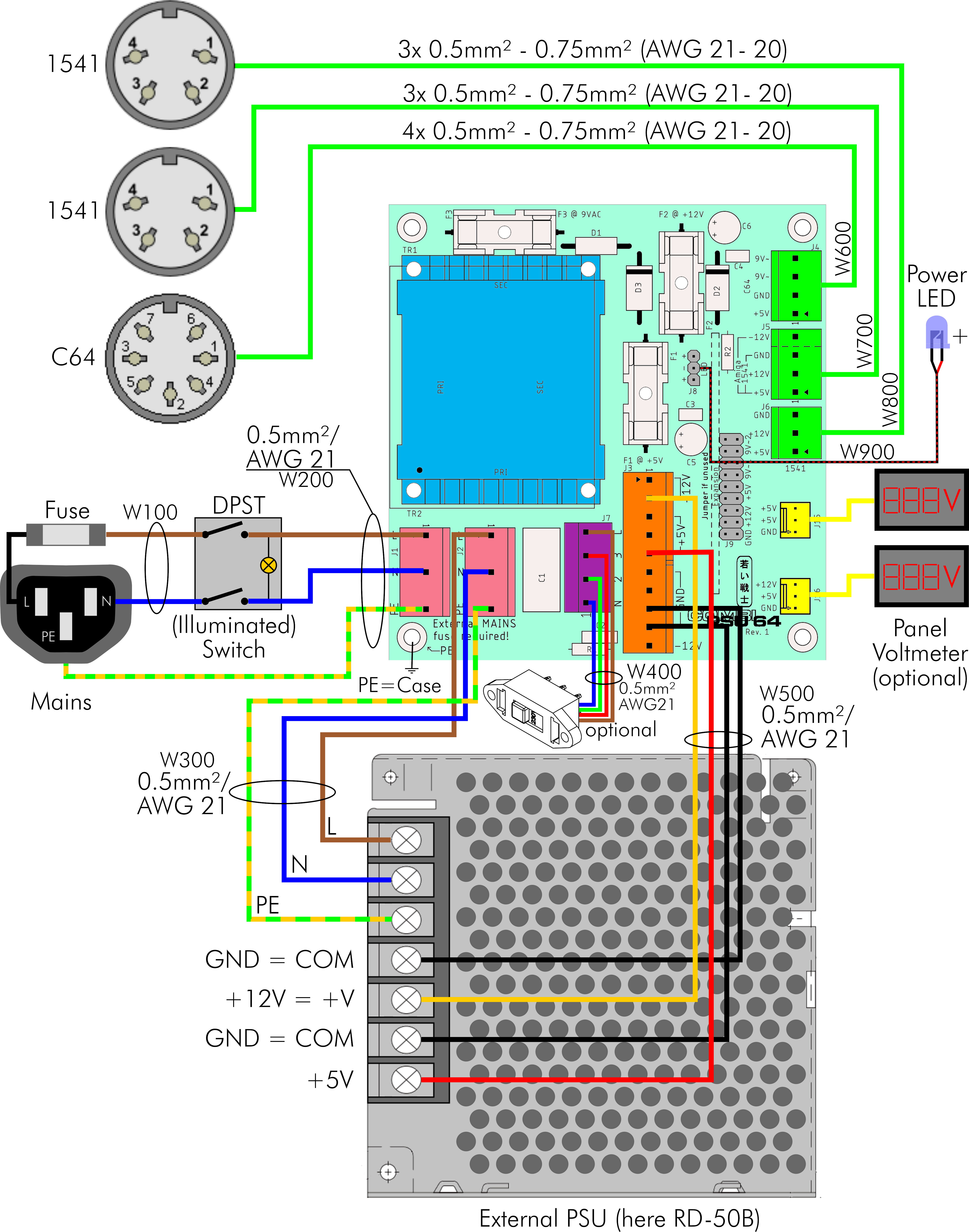
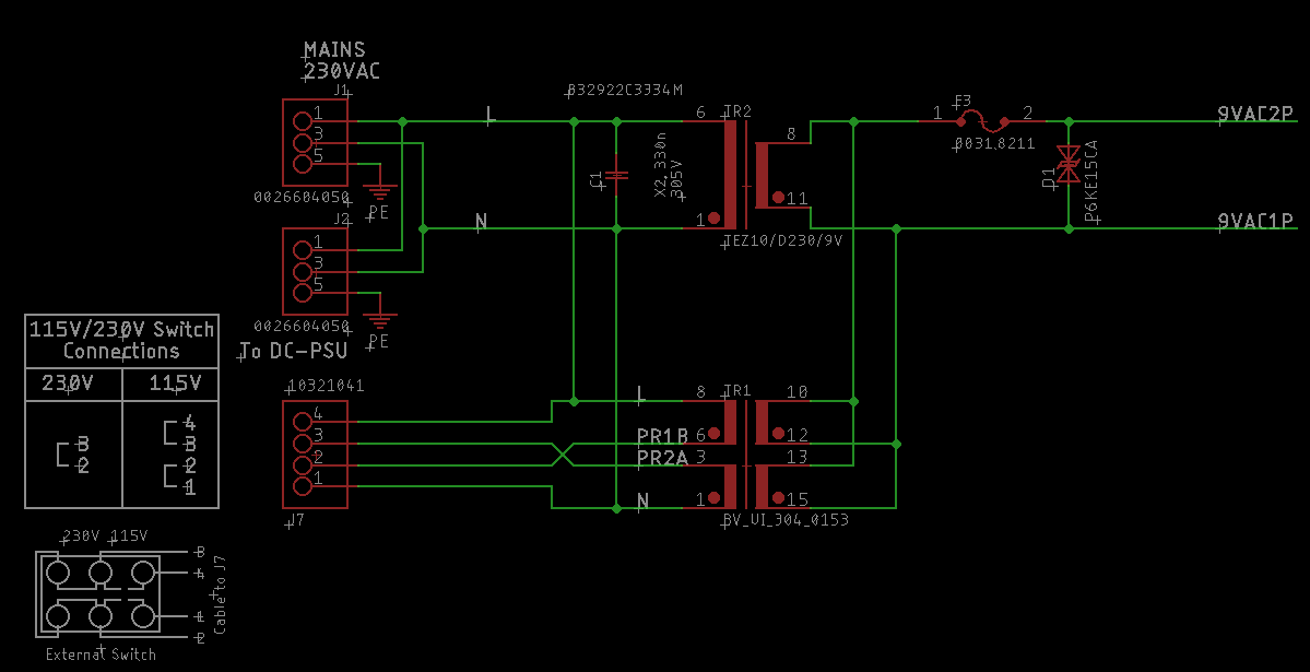
Wiring diagram of the C64 PSU Combi (Rev. 1)
Originally, I thought, it would be a good idea to connect those panel meters with a voltage and current display. The current would definitely an interesting information. I have added some connectors for it without really doing any research on those panel meters. I did not realize, that the current measurement was low side only, which is actually a bit unusual for current measurements. I did not find any panel meters, that were doing this job. And a low side measurement (between GND and the minus terminal of the load) does not work, when you have to monitor two voltages, that relate to the same ground.
I also found out (in a different project), that the current measuring panel meters are not worth the air, that they displace. I had two different models from two different sources. Both current measurements were so far off, that it was not possible to adjust them right.
So, I have dropped the current connectors for the sake of wide copper tracks.
Voltage drop is a topic, that needs to be taken into account with all power supplies. Most of it happens over the cable to the load (C64). The AC/DC modules, that many replacement power supplies base on (like my C64 PSU Global), produce exactly 5.00V. Sounds good, but might cause a problem with a few C64s.
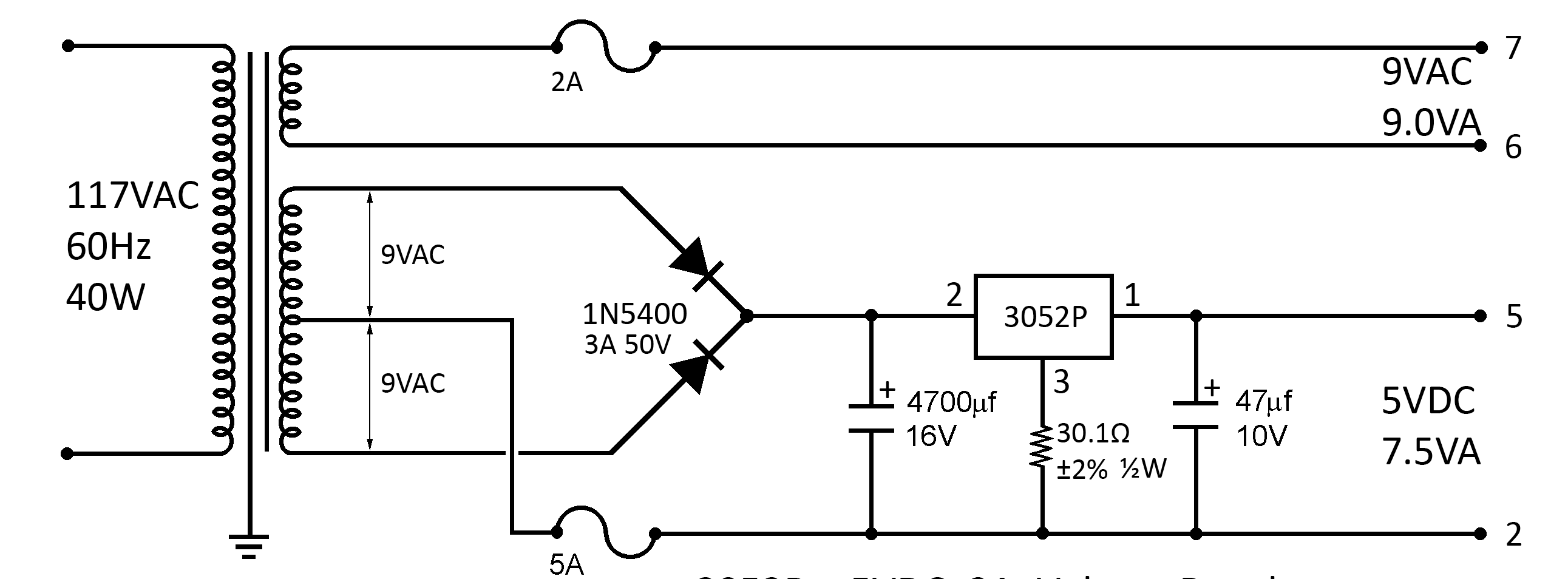
Original C64 Power Supply
The original power supplies output 5.2 to 5.3V on the 5VDC Pin. This is an intended feature. I don't know, if that was really required or if it is just a precaution. The 30.1Ohm resistor at the ground lead of the (5V) regulator increases the output voltage a bit. The additional 0.2V are the reserve for the voltage drop. Lets assume, that the current drawn on the 5VDC is 1A, which is close enough to reality. I have measured about 840mA (ASSY 250407 and 250425).
An AWG21 (0.5mm²) cable has a resistance of 43.4mOhm per meter. The output cable of the original PSU is about 1.5m long. Since the voltage drops on the 5VDC cable as well as on the GND cable, that sums up to 3 meters. The calculation is easy: 130mOhm (3 x 43.4mOhm) at 1A result in a voltage drop of 130mV.
BTW: regular PC power supplies output 5.1V on the 5VDC terminals. I have built quite a lot of industrial PC in my job. Many boards do not work with exactly 5.0V.
Anyway, what I actually wanted express is, that the RD-50B has an adjustment pot for the 5V. I suggest to set it to 5.2V (of course, without a C64 being connected, since it is easy to temporarily set it too high while adjustment.
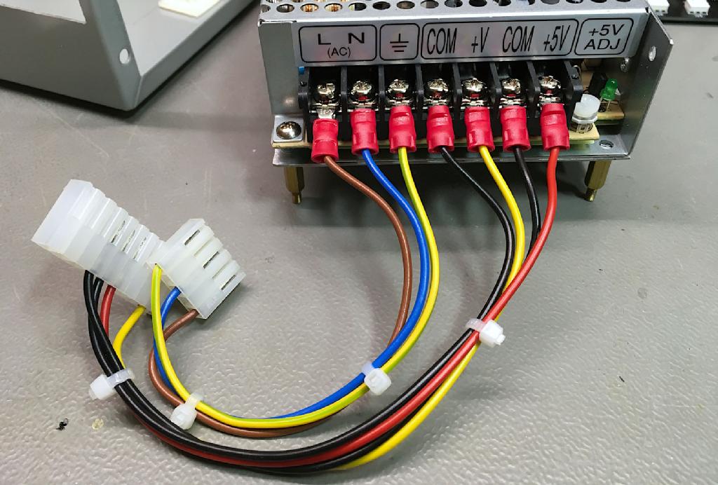
The terminals of the Mean Well RD-50B and the adjustment pot (+5V ADJ)
Since most DC PSUs, like the RD-50B have a wide range input (like 85V to 264V mains voltage), it was worth considering the use of a transformer, that is capable of being switched between 115V and 230V. This feature was added in Rev. 1 of the board. In Rev. 0, I already had the choice of two transformers. But it was the choice between a transformer available from reichelt.de and another transformer, which is available from tme.eu.
Except from the schematics: The transformer options
TR1 is the switchable transformer. It has two primary (=mains) windings and two secondary windings (=9VAC output). Each secondary winding is capable of 9V and 550mA. So they need to be ion parallel to get 1.11A output current (the original PSU is rated 1A). The trickery goes on with the primary windings. They are in parallel for 115V and in series for 230V. In both cases, the orientation is important. In parallel, pin 1 and 6 are connected and pin 3 and 8. In series, pin 6 is connected to pin 3. This is done with a switch on connector J7.
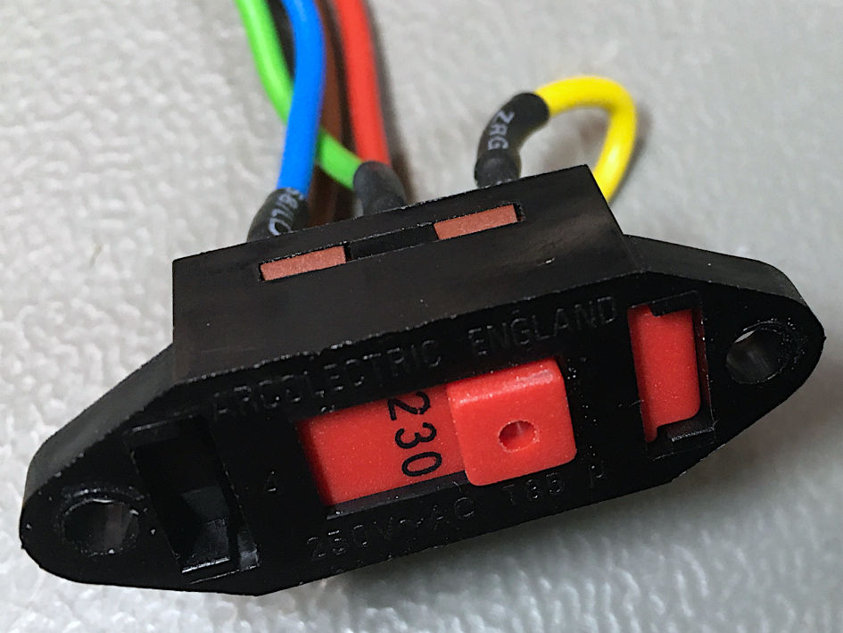
The mains voltage selector switch
Mains voltage is something for professionals! It requires certain distances on the PCB. Those distances depend on the specification of the device. I assume, that this device is operated below 3000m above sea level and the degree of contamination is little. So, I have used a minimum distance of 5mm between L(ive) and N(eutral) in case it is 230VAC and 2.3mm for 115VAC. Choosing the connector type for J7 was not trivial. Finally, I have picked a SPOX 5.08mm pitch connector for this.
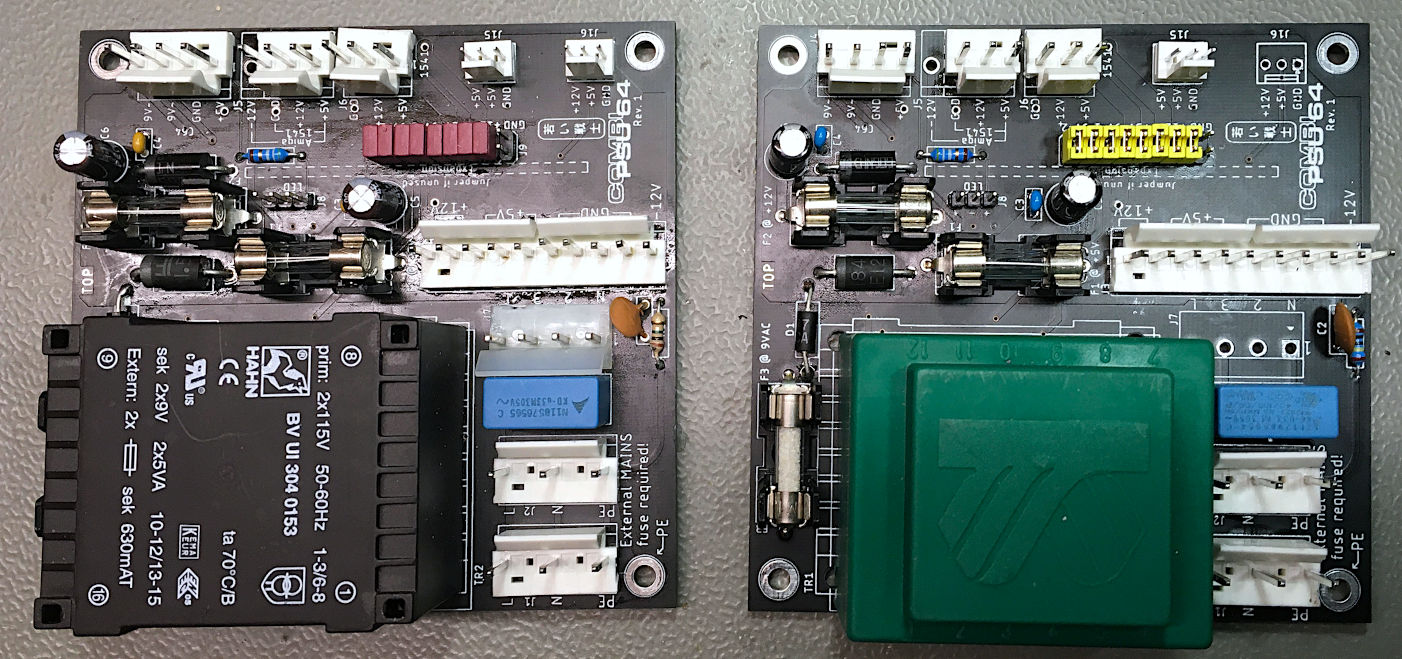
The two versions of the PCB
The previous image shows both versions of the PCB. On the left you see the 230V/115V version, on the right the 230V only version.
The green transformer is slightly cheaper than the black. Both are available from tme.eu. The 230V version does not require a mains voltage selector, so J7 is not populated.
The middle output connector (J5, on top) can be three pins for a 1541-II or four pins for an Amiga, which requires additional -12V (and an RT-65B DC PSU).
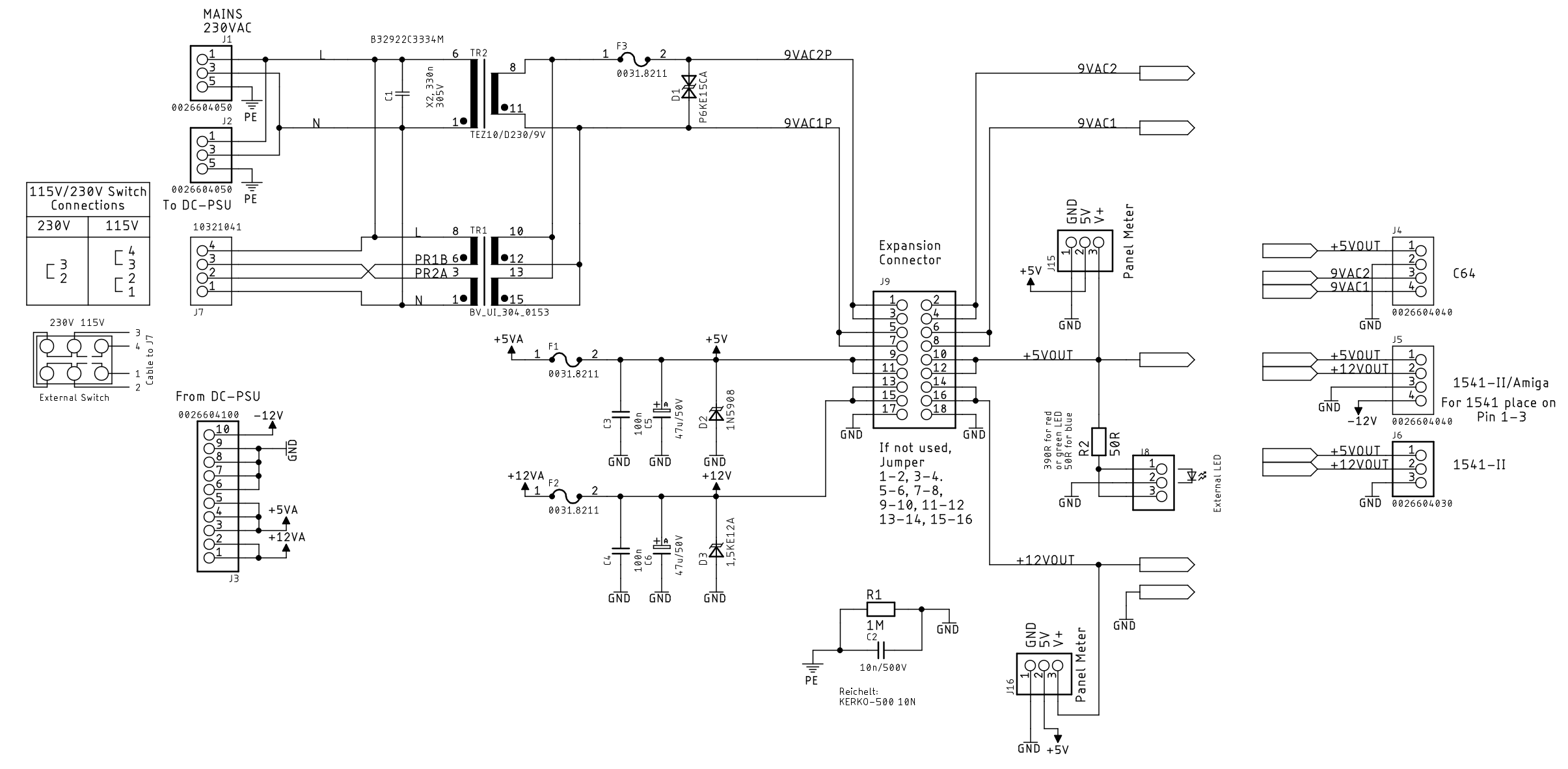
The schematic of the C64 PSU combi
This picture shows the schematics of the PSU combi. I already mentioned the alternative transformers. The 9VAC are protected with a bi-directional TVS diode. This is a protection against voltage spikes and a very basic protection against overvoltage. A defective transformer, that outputs a too high voltage is not really likely.
The +5V and +12V are protected with a uni-directional TVS diode, each. Again, this is not a saver or a real over voltage protection.
The Expansion Connector J9 is for later use. Here, a proper over voltage protection of a current and voltage measurement can be installed. Those are not developed yet (as of April 2020). Until something useful is connected, J9 is jumpered. This can be seen on the picture, which is showing the two versions of the PCB.
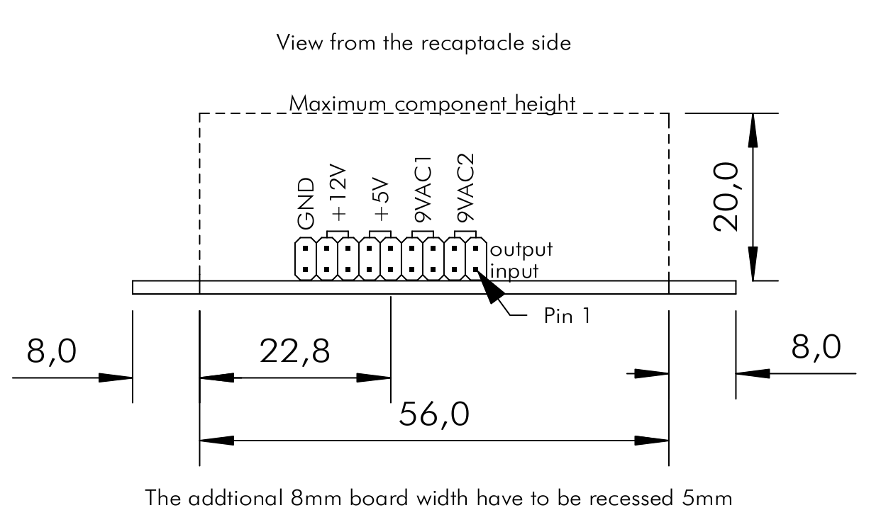
Dimensions of the expansion module.
The PSU was designed to fit into a metal case. An inexpensive one is the Hammond 1411P, which offers a compact design with the RD50B DC-PSU and the PCB. It has to be customized with a few cut outs and drills. Further a mountig plate for connectiong the PCB to the DC power supply and an angle profile is required. Templates for dimensioning the cutouts are included in the documentation.
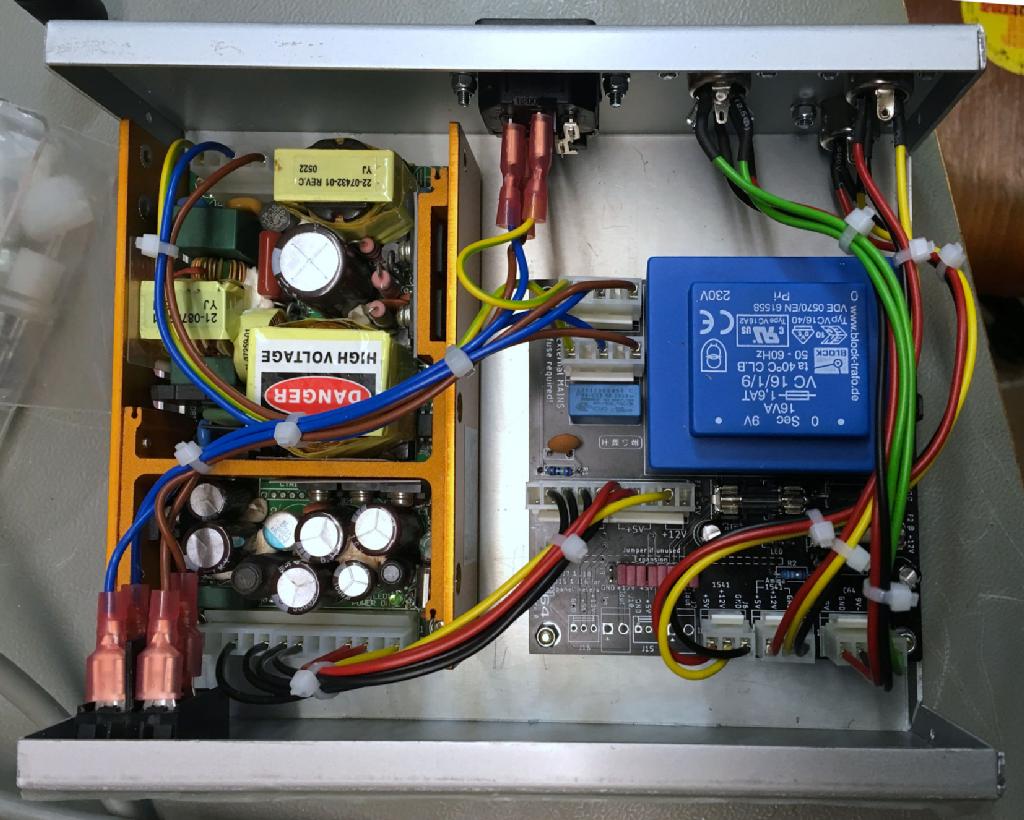
View inside the Hammond 1411P case
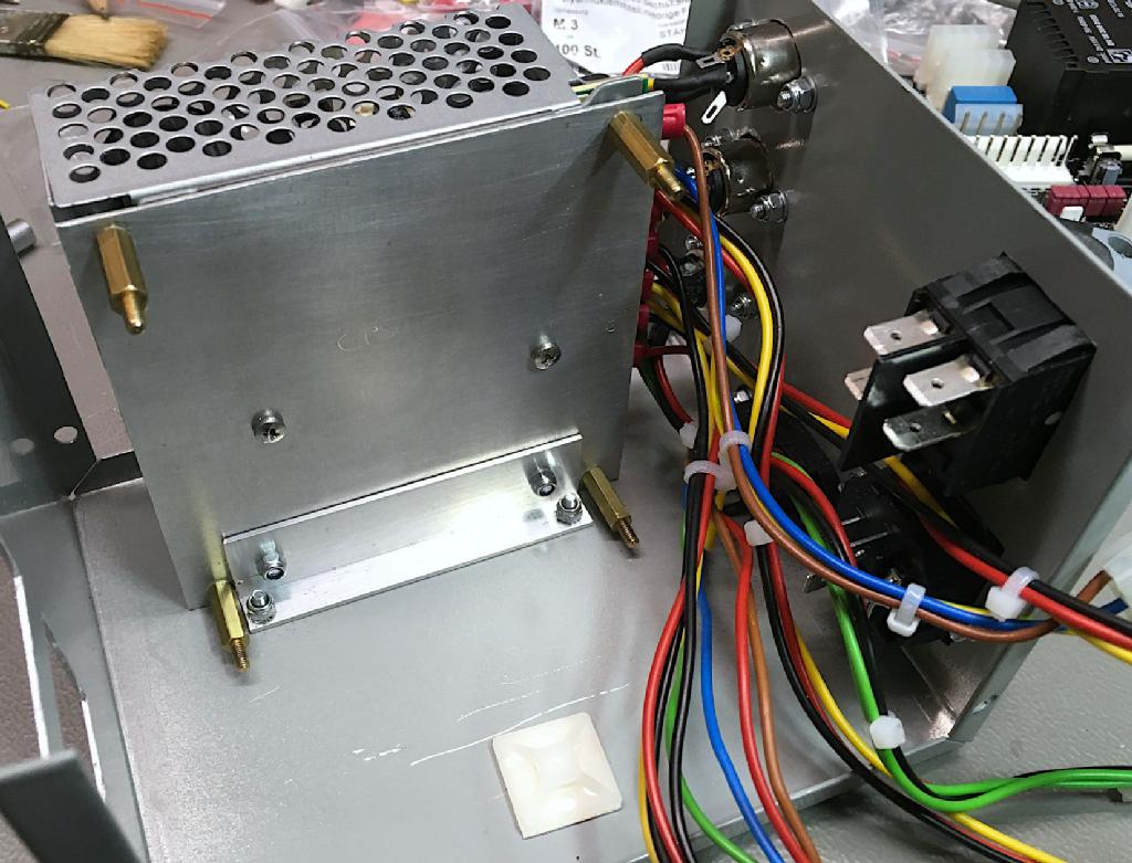
RD-50B with the mounting plate and the angle profile
C64 PSU combi in a TEKO 382 case with a XPower open frame DC PSU
Further thoughts on the C64 PSU combi:
1. A module for the expansion port will be released some time in the future. I am planning to measure all voltages and currents and displaying them on an LCD display on the front. It will be arduino based. Maybe I put a Pro Micro on this module.
2. As soon as I get some USB connectors (panel mount ones) from the other end of the silk road, I will mount one on the backpanel. There will be 5V available on them for powering the RetroTINK -2X, which I use as an S-Video to HDMI converter. This means one power switch for everything and one more saved outlet.
Rev. 0, Rev. 1 and Rev. 2 are fully functional and well tested. Find the documentaion on my github repository.
Rev. 1 and 2 are fully documented, the documentation of Rev. 0 will stay as is.