


PET Ultimate Expander
Content
Introduction
The PET Ultimate Expander serves the following purposes:
At present (07/2023) it is a project under development. It is partially tested and the user interface is being programmed (60%).
The Ultimate Expander is installed on the internal bus connectors J4 and J9. The position of J4 and J9 is relative to each other not the same in the CRTC board and the non CRTC board. So there is an extra break out PCB for J4, which is connected via a short ribbon cable to the Ultimate Expander.
Introduction
The PET Ultimate Expander serves the following purposes:
- 32kByte RAM Expansion (option: battery buffered)
- EPROM Adapter
- Reset/Diagnostic/NMI-Switch pin header
- Audio (from User Port CB2) output
- EPROM configuration interface with user interface
- Light pen interface (CTRC only)
At present (07/2023) it is a project under development. It is partially tested and the user interface is being programmed (60%).
The Ultimate Expander is installed on the internal bus connectors J4 and J9. The position of J4 and J9 is relative to each other not the same in the CRTC board and the non CRTC board. So there is an extra break out PCB for J4, which is connected via a short ribbon cable to the Ultimate Expander.
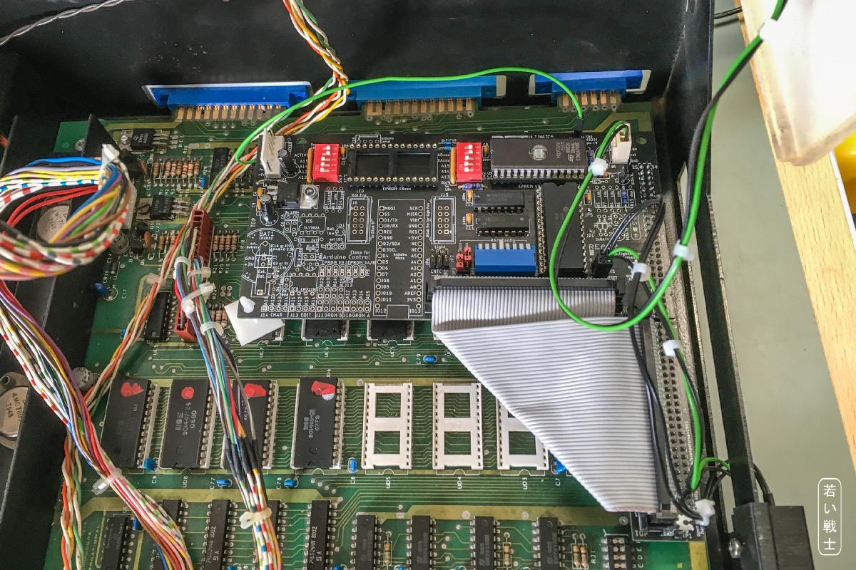
Ultimate Expander Rev. 0 instralled in a CBM3016 (non CRTC, 2001-N series)
J4 and J9 do not offer a +5V supply voltage, but there is this J11 connector on the main board, which offers an unregulated DC voltage. This is "conditioned" with a 7805 linear voltage regulator to supply the digital circuits on the UltiEx.
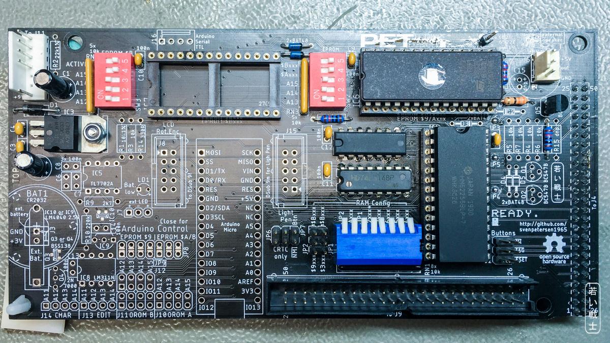
UltiEx Rev. 0 (not fully populated). The linear regulator is top left.
The functional blocks are marked on the bottom side of the board, so it should be possible to populate teh board to the needs. E.g. a non CRTC PET does not have any light pen functionality, so it is not required to polupate it. The CRTC PET does only support an external EPROM at $9xxx, so the other EPROM sockets are not required. In case it is not intended to battery buffer the RAM, the battery circuit is not required.
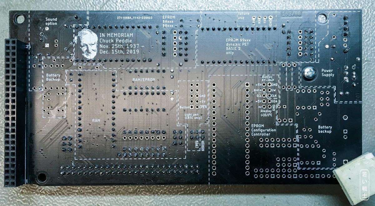
UltiEx Rev. 0 - bottom side
The purpose of the battery buffered RAM is emulating an EPROM. The (EPROM) content can be loaded via the TIM monitor in case some expansion RAM is mapped to the address space of the EPROMs ($9xxx, $Axxx, $Bxxx). This should make trying out some EPROMs more fun.
Some of the 40 column machines provide less than 32k of RAM. The eight 4k RAM blocks of the UltiEx can be mapped to these addresses:
- $2xxx
- $3xxx (or $Bxxx)
- $4xxx
- $5xxx
- $6xxx
- $7xxx
- $9xxx (or $Bxxx)
- $Axxx
Like most Commodore computers, the PETs are lacking a RESET switch. A reset is not even found on the user port, the only "accessible" reset can be found on J9, so it is a essential things to have a pin header on the UltiEx to provide the signals for RESET, DIAG and NMI. I already have designed "non invasive" button holders, which can be attached to the side of the bottom case without drilling or glueing.
The CRTC provides a light pen input. There is a 10 pin box connector, which allows to attach a DSub with the relevan pins at the same location like the VIC-20 or C64, so it should be possible to attach a C64/VIC-20 light pen to the UltiEx. This feature is not yet tested.
Most PET programs, that provide sound (and the piezo speaker on the 8032 boards) are connected to the user port/VIA pin CB2. UltiEx provides a little circuit, that allows to attach an external or opn board piezo to CB2. The VIA signal CB2 (6522, pin 19) has to be connected via a short jumper cable. A pin header provides +5V, audio and GND, so it is possible to connect a little audio amplifier module and a speaker to get a louder output. it might also be desirable to connect the piezo to a higher voltage to get more volume. This will be incorporated in a possible redesign of the board.
Most EPROM adapters hold EPROMs, which provide more than 4k (which is the side of the ROM fitting into the socket on the PET mainboard (2k for the EDIT ROM). Usually, there are jumpers to select the EPROM memory block (oe of multiple software), that is mapped to the ROM socket. Jumpering requires opening the PET and setting the jumpers while power off. So, it is desirable to have a user interface (UI), which does the ROM configuration/selection with buttons or a rotary encoder. The UltiEx provides a socket for an Arduino micro (not "pro micro") and a 10 pin box connector to connect an external user interface.
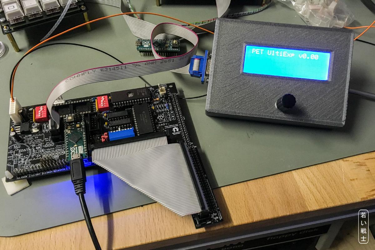
UltiExp (Rev. 0) with user interface on the work bench (externally powered for software development)
The User interface consist of a standard 4x20 LCD dispaly with I²C input, a KY-040 rotary encoder (wide spread module) and a cable. The box connector/dsub has a pinout, that allows to slpit the attached internal cable in 5 wires and 4 wires for the display and the rotary encoder respectively. This way, it does not require a PCB inside the user interface to do a proper installation.
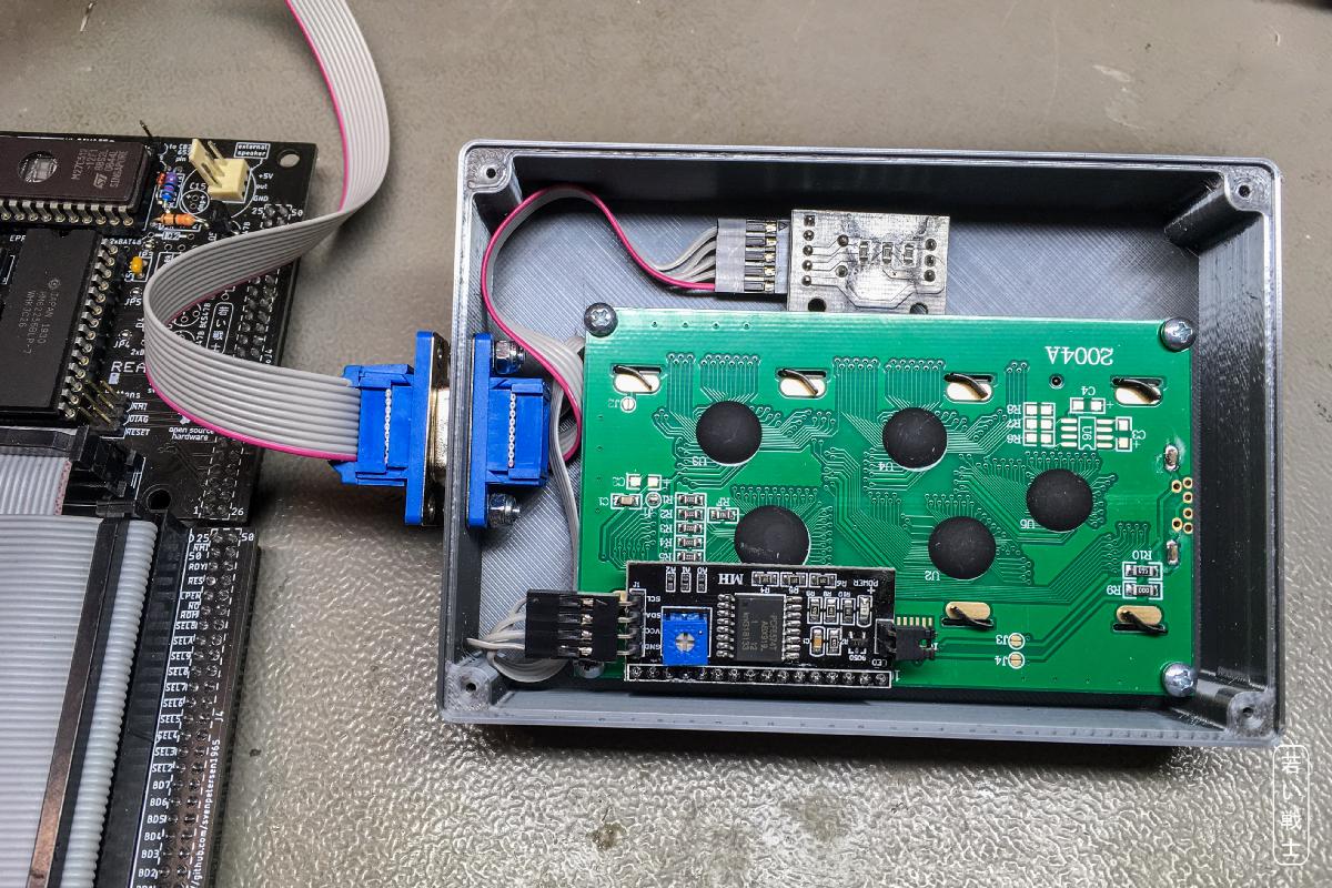
Open UI with display (bottom) and rotary encoder (top)