


PET/CBM Diagnostic Clip
Content
Introduction
CRTC-PETs
Non-CRTC PETs
Literature About The Diagnostic Clip
The Diagnostic Software
CBM8296
This Project On Github
Introduction
Some time ago, I have found out, that there was a diagnostic clip for the PET and CBM computers. Since diagnostics is actually my favorite Commodore topic, I have searched the internet about what I could find out about it.
The clip is a little box, which contains some test software and address decoding for the EPROM, that is holding the software. It connects to a test clip, which then fits on the 6502 CPU of the PET/CBM.
CRTC-PETs
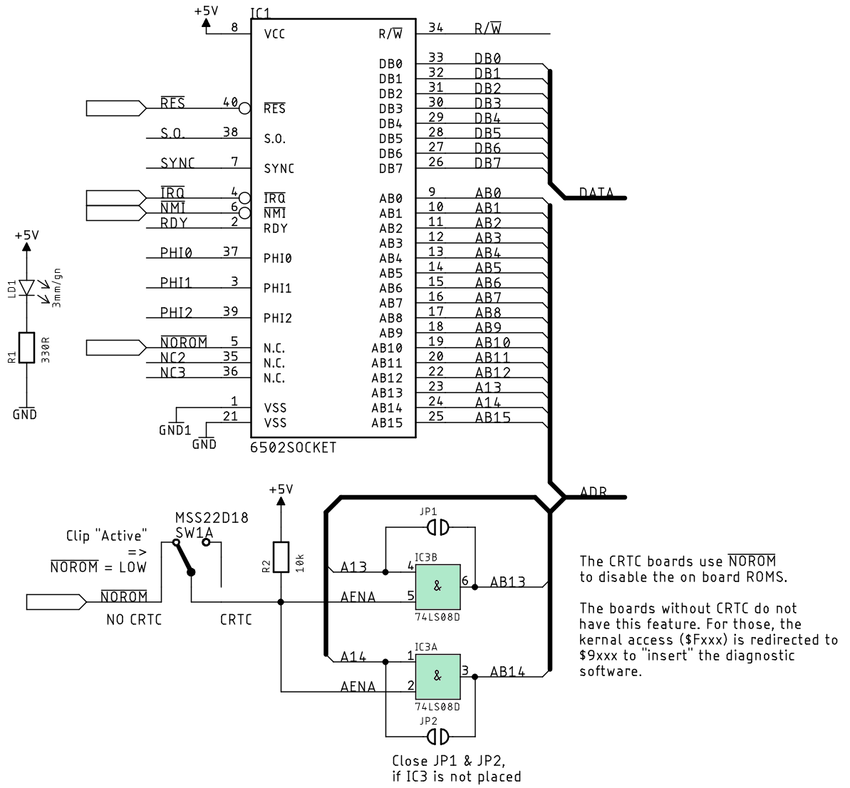
As I have mentioned in the page about the 2332 EPROM adapter, there is this signal "/NOROM". When this gets low, all ROMs (except the character generator ROM) are switched of. The test software can be found at address $Fxxx (that is, where usually the kernal is located) and it is executed on startup.
Introduction
CRTC-PETs
Non-CRTC PETs
Literature About The Diagnostic Clip
The Diagnostic Software
CBM8296
This Project On Github
Introduction
Some time ago, I have found out, that there was a diagnostic clip for the PET and CBM computers. Since diagnostics is actually my favorite Commodore topic, I have searched the internet about what I could find out about it.
The clip is a little box, which contains some test software and address decoding for the EPROM, that is holding the software. It connects to a test clip, which then fits on the 6502 CPU of the PET/CBM.
CRTC-PETs
As I have mentioned in the page about the 2332 EPROM adapter, there is this signal "/NOROM". When this gets low, all ROMs (except the character generator ROM) are switched of. The test software can be found at address $Fxxx (that is, where usually the kernal is located) and it is executed on startup.
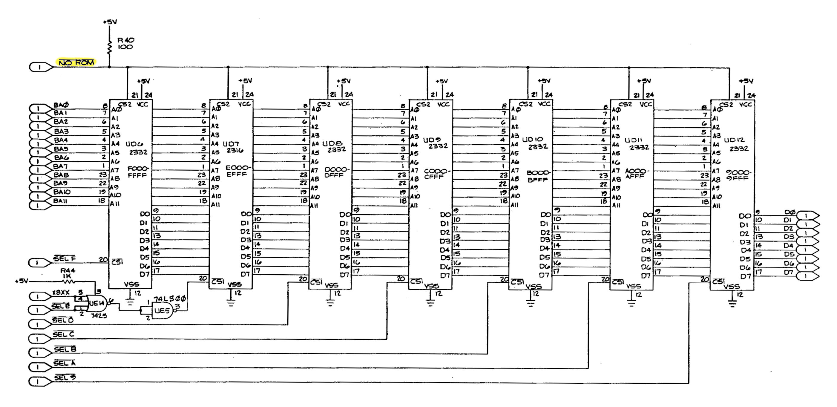
The /NOROM signal switches off all ROMs, in case it is LOW.
The /NOROM signal is connected to the CPU, Pin 5, wich is an "n.c." (usually unused) pin. It is internally not connected to the CPU chip. It can be switched by the diagnostic clip, though! And that does the trick of executing the code on the diagnostic EPROM instead of the kernal on start-up. (Note: It is further connected to Pin 20 of the memory expansion connector J4.)
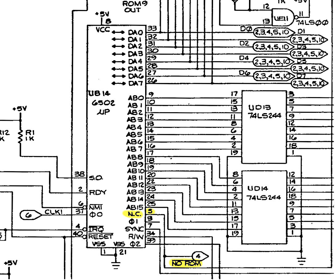
/NOROM at Pin5 of the CPU
There are two different clips for the PET and the CBM that I have found schematics for.
Sources:
● http://www.6502.org/users/andre/petindex/diag/index.html
● http://www.zimmers.net/anonftp/pub/cbm/schematics/computers/pet/diagnostics.txt
I have tried to combine both version to my own schematics.
Sources:
● http://www.6502.org/users/andre/petindex/diag/index.html
● http://www.zimmers.net/anonftp/pub/cbm/schematics/computers/pet/diagnostics.txt
I have tried to combine both version to my own schematics.
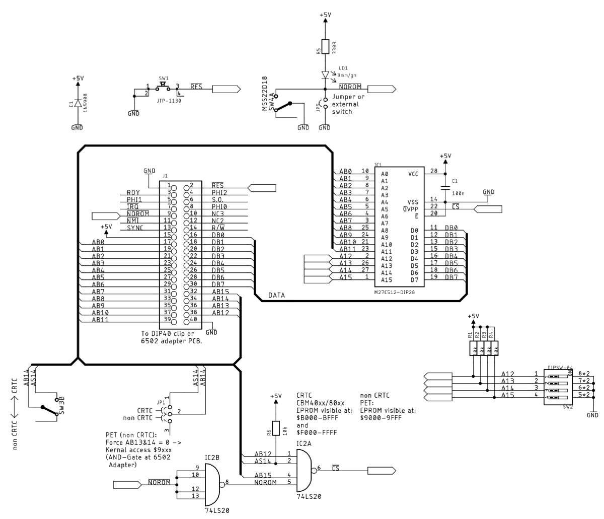
The EPROM is a 27C512 (or 27C64, 27C128, 27C512). I did not use a 74LS138 for the chip selects, but two NAND gates with four inputs each, because I did not use two EPROMs, it only requires one chip select signal. The diagnostic software can be selected with a DIP-Switch. The switch no. 5 is activating/deactivating the clip.
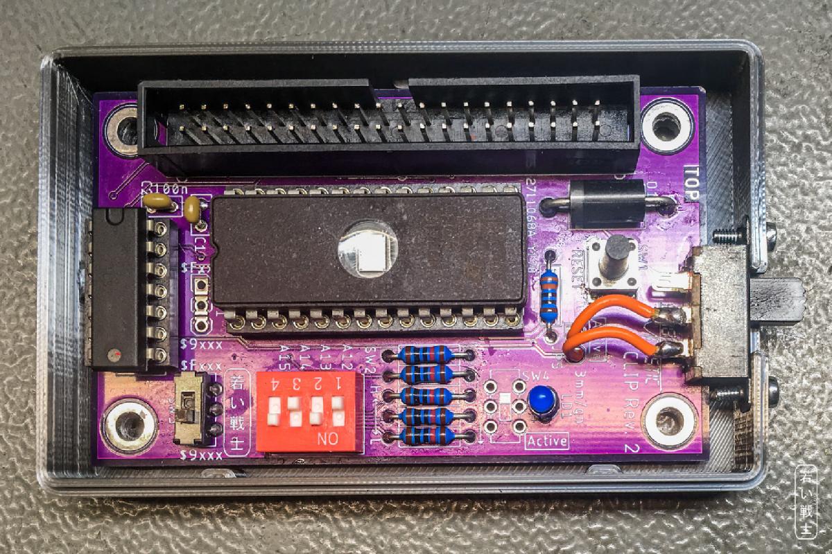
Test clip PCB Rev. 2
Of course, a 3D-printed case is helpful to prevent any short circuit, when placing the clip PCB inside the computer.
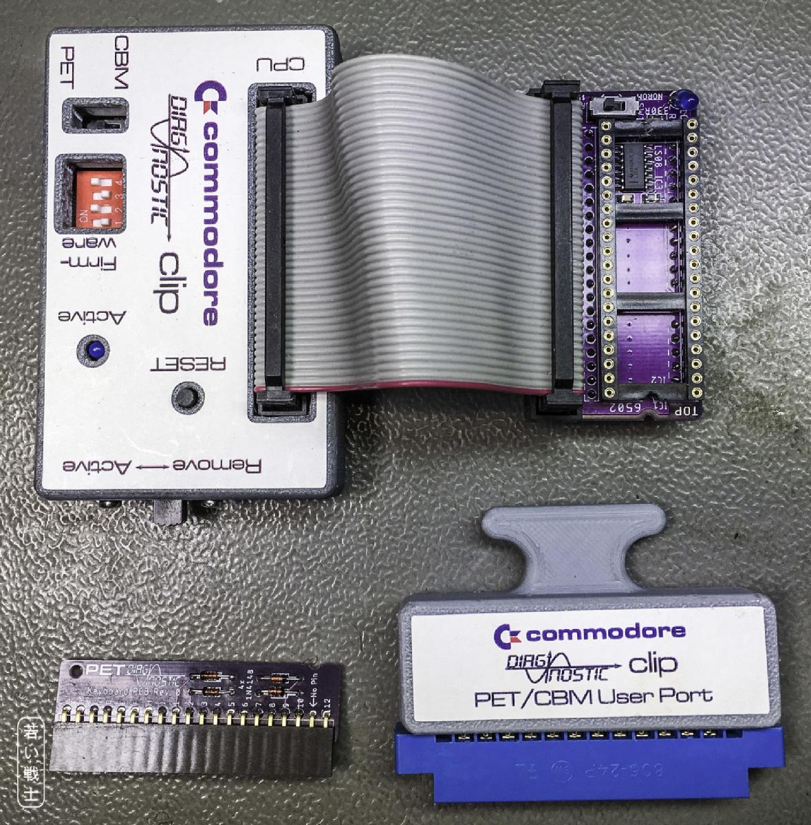
The diagnostic PCBs with cases and labels. The diagnostic clip is Rev. 2
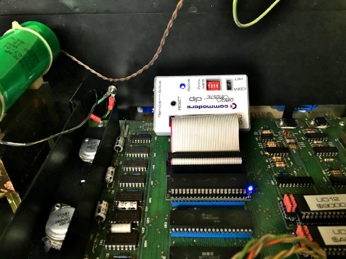
The diagnostic clip and the CPU adapter installed in a CBM8032
The test clip for a DIP40 IC is pretty expensive (around US$50), so I have also made an adapter boartd for the CPU. This fits between the IC and the socket on teh main board. It allows to connect a ribbon cable, which is a way cheaper solution. The CPU is usually on a socket. I was told, that the originally clip solution is not really reliable and it sometimes takes more than one attemt to pull off the clip without crashing the software.
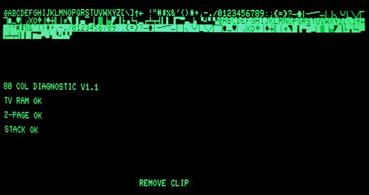
Test Results - Page 1
After switching on and the CRT warming up, the first test results are visible. This is the test of the character ROM, the video RAM, the zero page and the stack page. Not very spectacular. And that was all I could get. Was ist worth the hassle to develop the clip? I was not sure and thought of dumping the project or writing my own test software.
I went through the disassembly of the EPROM content and saw, that the programming is pretty special. No subroutines were used, because that would require a healthy stack, which is not proved in the beginning. Also the dispalyed texts were stores as screen codes (not ASCII), because it does not use any kernal subroutines (there is no real kernal at this moment of the test, it is switched off with /NORAM = LOW).
The other day, I have then done, what is requested. I have "removed" the clip. It cannot physically be removed, because it is no clip, but it can be switched off with the DIP-switch. And wow! Something happened. It said "no irq". Ok... but I didn't have the user port dongle and the keyboard dongle installed,. yet. Which I then did. And...
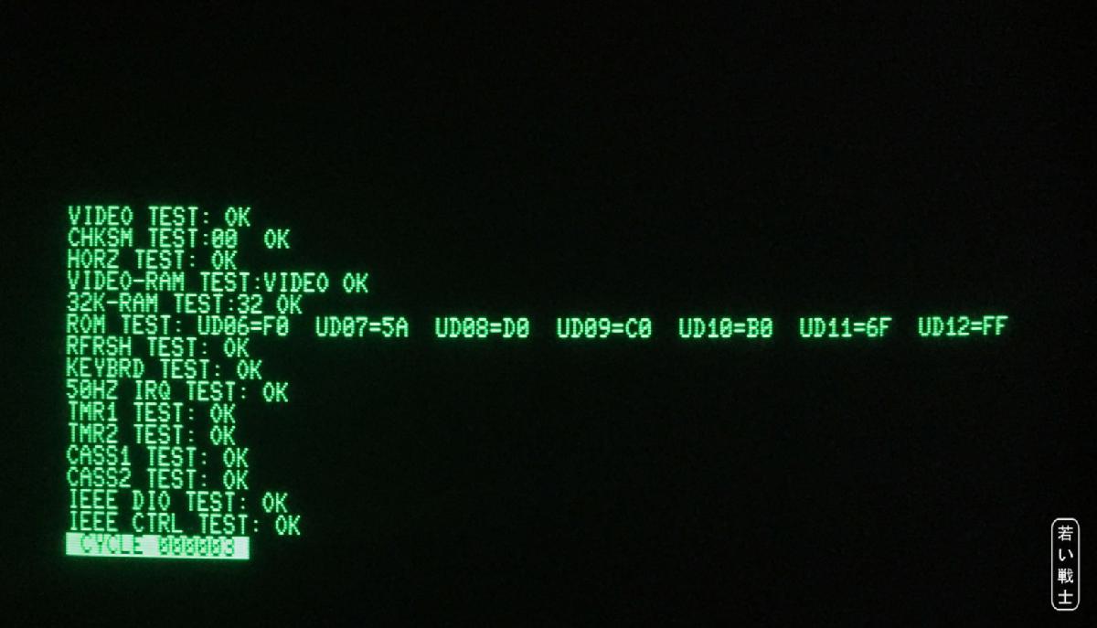
Test Results - Page 2
The 2nd page appeared. All in a sudden, the development made sense to me. Switching off the clip is even easier than pulling off a test clip.
First, there was still a test failed (SRQ bad), which stopped the test execution, but after replacing the 6520 (PIA) for the IEEE-488 port, the test was passed flawlessly and started looping.
Further, I have tested different software versions, that I have found. One is v1.1 for the 80 column computers (8032 and 80col 40xx). The other is v2.0 for the 40 column (40xx, 30xx) computers. I have tested those on VICE (only the first half, since I don't know, hot to mimic the dongles in VICE) first.
Non-CRTC PETs
The 40 column, non-CRTC machines cannot switch off the ROMs, so they use another way to force the copmputer to run the diagnostic software:
The address bits A13 and A14 are forced LOW (by shorting them to GND). A kernal ROM accress (at $Fxxx) is redirected to $9xxx. This way, the reset vector of the CPU, which is usually found at $FFFC is redirected to $9FFC. In the diagnostic EPROM, it points to $9800, the entry point of the diagnostic software.
Tying those address bits to GND is most probably not harmfull, but since I don't have any schematics of the port pins inside the 6502, I cannot confirm this theory. So I have decided to redesign the 6502 ribbon cable adapter with AND gates in teh A13 and A14 address signals. They issue a LOW in case the /NOROM signal is LOW, as well.
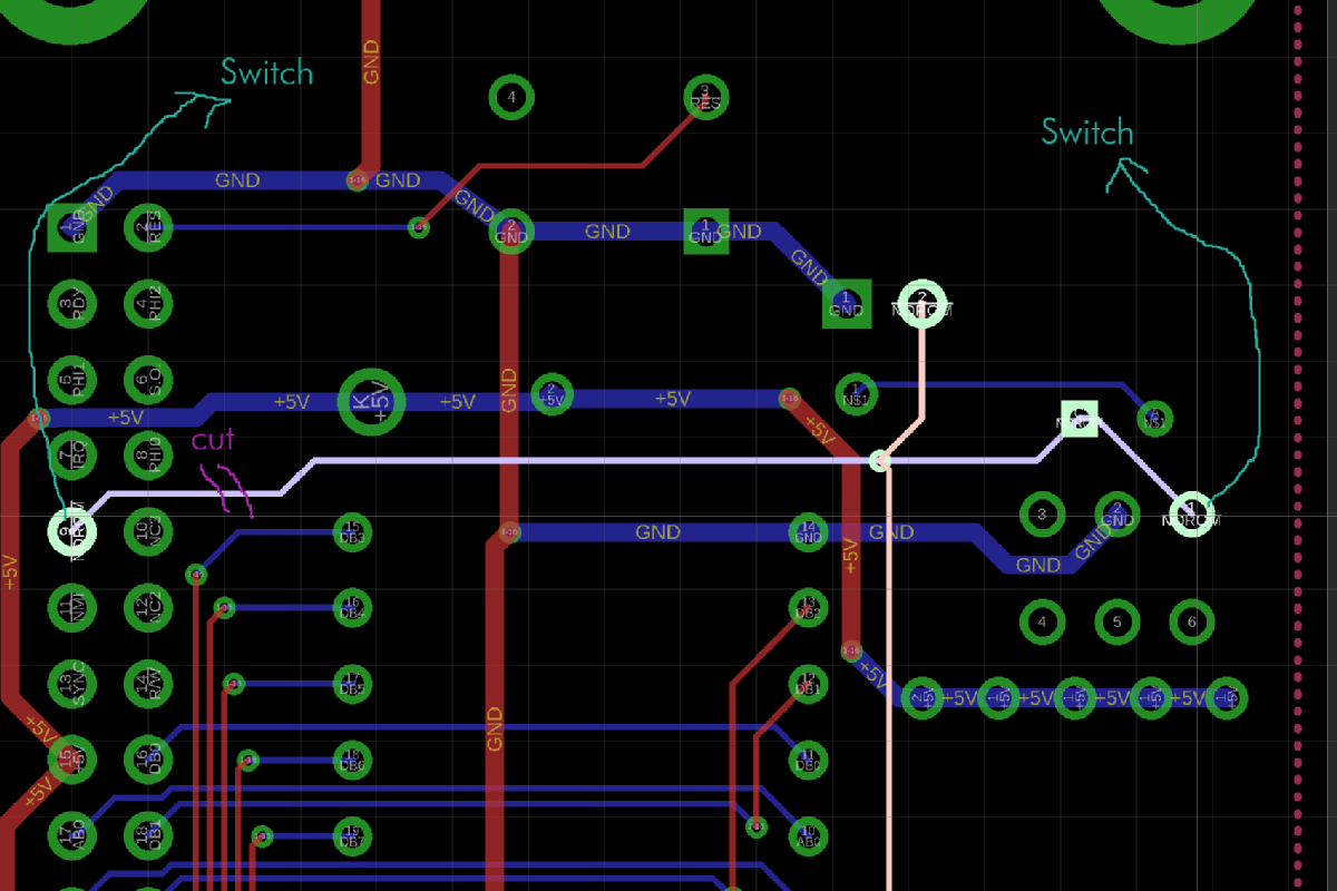
Excerpt of the 6502 Ribbon Cable adapter Rev. 1
The said AND gates in the above figure are marked. In case the switch SW1 selects Non-CRTC, the /NOROM signal is connected to one input of each AN-Gate, so the ouputs AB13 and AB14 are permanently low, as long as the Clip is active. In case the Clip is "removed" = not active or CRTC is selected, the and gates are transparent for A13 and A14.
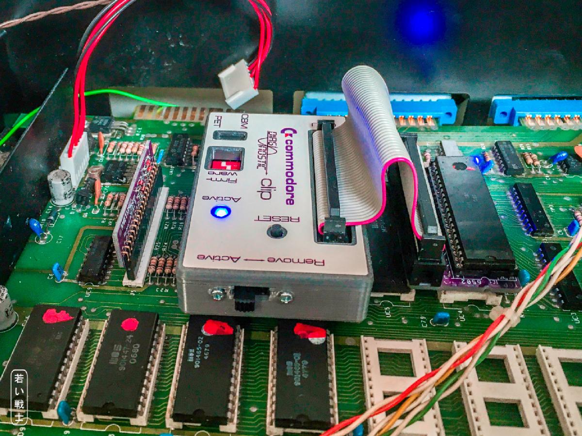
Diagnostic Clip inside the CBM3016
With this configuration, the Diagnostic Software is executed properly.
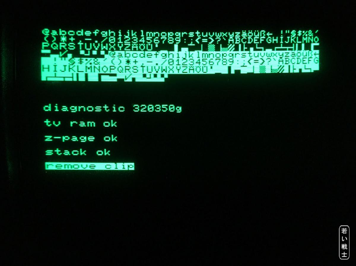
Diagnostic 320350g (non-CRTC, 40 col.) start
After switching the Diagnostic Clip Board to "Remove", the actual test is carried out. The test is scrolling the screen and if finished without detecting a problem, it is looping. The loop counter is displayed.
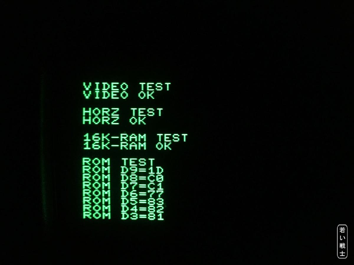
First part of the test loop
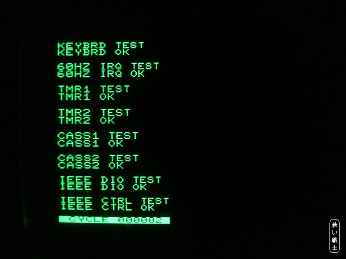
2nd part of the test loop, the loop counter is the last entry.
Literature About The Diagnostic Clip
First, I didn't find anything about the diagnostic clip in the literature, at least no realy test description. Finally, I have found a few hints in "Testing the PET Computer" and especially in the "Commodore Training_40xx_80xx_Service Manual" on Carsten's great retro-commodore.eu website (where you can find high quality scans of manuals and tech docs.
Unfortuntately, this is a German document, so I have translated it to English.
Page 33ff:
"DIAGNOSTIC-BOX BESCHREIBUNG
Die Diagnostic-Box ist ein Testgerät, mit dem die wichtigsten Komponenten auf der Logic-Platine der Zentraleinheiten getestet und ein hoher Prozentsatz der Fehler gefunden werden kann.
Die Tastatur selbst und das Video-Board wird nicht überprüft. Für jede Zentraleinheit gibt es eine spezielle Diagnostic-Box
Anschluß und Starten des Testprogramms:
Zur Diagnostic-Box gehören zwei Diagnostic-Stecker, einer für den User-Port und einer für die Tastatur. An der Box befindet sich ein 40-poliges Flachbandkabel mit einem IC-Clip.
Dieser Clip wird auf den Prozessor gesteckt und die beiden Diagnostic-Stecker kommen an die entsprechenden Positionen.
Wenn die rote LED leuchtet, kann das Diagnose-Programm durch drücken der roten Taste (Reset) gestartet werden.
Auf dem Bildschirm wird nun angezeigt welcher Test gerade läuft, ob er fehlerfrei durchläuft, oder was für Fehler erkannt wurden. Wird ein Fehler erkannt, stoppt das Testprogramm. Treten keine Fehler auf, werden die Tests laufend wiederholt."
Translated to English:
"DIAGNOSTIC BOX DESCRIPTION
The Diagnostic-Box is a test device with which the most important components on the logic board of the central units are tested and a high percentage of errors can be found.
The keyboard itself and the video board are not checked. There is a special diagnostic box for each computer.
Connection and start of the test program:
The Diagnostic Box includes two diagnostic plugs, one for the User port and one for the keyboard. There is a 40-pin ribbon cable with an IC clip attached to the box
.
This clip is put on the processor and the two diagnostic plugs are connected to the appropriate positions/connectors.
When the red LED lights up, the diagnostic program can be started by pressing the red button (Reset). The screen now shows which test is currently running and whether it is passed or failed, or what kind of errors were detected. If an error is detected, the test program stops. if there are no fails, the tests are repeated continuously."
[...]
"Testbeschrelbung
Nach Betätigung der Reset-Taste wird der CRT-Controller initialisiert und der CBM-Zeichensatz in den oberen Teil des Bildschirms geschrieben womit festgestellt wird ob es überhaupt möglich ist Daten auf den Bildschirm zu schreiben.
Nun wird Zero-Page und Stack getestet. Treten hier Fehler auf wird entweder ein RAM als defekt angezeigt oder eine Adressleitung.
Eine genaue Erkennung des Fehlers ist aber in manchen Fällen nicht möglich, sodaß zum Teil unrichtige Fehlermeldungen ausgegeben werden. Um den Fehler zu lokalisieren kann man die CAS-Leitungen an den RAM's vertauschen und den Test neu starten. Wird wieder eine Fehlermeldung ausgegeben, so liegt der Fehler wahrscheinlich nicht an den RAM', sondern an der Ansteuerung(Adressleitungen, Refresh, RAS, CAS,RAM R/W, MUX A).
Ist Zero-Page und Stack in Ordnung wird ein Testprogramm in den RAM-Bereich geschrieben und die Aufforderung REMOVE CLIP erscheint auf
dem Bildschirm.
Wird nun die Diagnostic-Box vom Prozessor entfernt, werden von dem in der Zero-Page befindlichen Testprogramm die weiteren Teile des Systens getestet. Die ausgegebenen Fehlermeldungen sind im allgemeinen zuverlässig."
English:
"Test description
After pressing the reset button, the CRT controller is initialized and the CBM character set is displayed on the upper part of the screen, which determines whether it is even possible to write data on the screen.
Now the zero-page and stack are tested. If errors occur here, either a RAM is displayed as defective or an address line.
In some cases, however, an exact detection of the error is not possible, so that in some cases incorrect error messages are output. To localize the error, you can swap the CAS lines on the RAM's and restart the test. If an error message is output again, the error is probably not due to the RAM, but to the control (address lines, refresh, RAS, CAS, RAM R / W, MUX A).
If the zero page and stack are OK, a test program is written to the RAM area and the REMOVE CLIP request appears the screen.
If the diagnostic box is now removed from the processor, the other parts of the system are tested by the test program in the zero page. The error messages issued are generally reliable. "
Ok, now it is obviouzs, that removing (or deactibvating) the clip is requires to complete the test. Now, the 2nd page of the test results appears. It also says, that the etst software was written to the zero page previously.
CHKSM TEST: Um zu überprüfen, ob das Testprogramm richtig in die Zero-Page geladen wurde, wird eine Prüfsumme gebildet die 00 ergeben muß.
VIDEO RAM TEST: Es werden in jede Bildschirmadresse Daten geschrieben wieder gelesen und verglichen
32K RAM TEST: Es wird der gesamte RAM-Speicher ausser Zero-Page und Stack getestet
ROM TEST: Es werden Prüfsummen von jedem ROM gebildet (siehe Liste der Prüfsummen)
RFRSH TEST: Es werden Daten in die RAM's geschrieben, eine zeitlang gewartet und die Daten wieder ausgelesen. So wird überprüft, ob der Refresh in Ordnung ist.
KEYBOARD TEST: Es wird die Funktion des Decoders und des PIA überprüft
50 HZ IRQ TEST:Es wird getestet, ob von dem Signal Vert Drive über den PIA Interrupts erzeugt werden.
TMR1/2 TEST: Es werden die beiden TIMER des VIA getestet
CASS1/2 TEST: Es werden die beiden Cassetten-Ports getestet Beim Lesen werden Interrupts erzeugt COTA_PIR)
IEEE Tests: Es werden Daten und Steuersignale getestet. Die IEEE-Buffer werden mitgetestet
English:
CHKSM TEST: In order to check whether the test program has been loaded correctly into the zero page, a checksum is formed which must result 00.
VIDEO RAM TEST: Data is written to each screen address, read back and compared
32K RAM TEST: The entire RAM memory except for the zero page and stack is tested
ROM TEST: Checksums are generated from each ROM (see list of checksums)
RFRSH TEST: Data is written to the RAMs, waited for a while and the data is read out again. This checks whether the refresh is OK.
KEYBOARD TEST: The function of the decoder and the PIA is checked
50 HZ IRQ TEST: It is tested whether interrupts are generated by the signal Vert Drive via the PIA.
TMR1 / 2 TEST: The two TIMERS of the VIA are tested
CASS1 / 2 TEST: The two cassette ports are tested When reading, interrupts are generated COTA_PIR)
IEEE Tests: Data and control signals are tested. The IEEE buffers are also tested
There is another, different version of "Testing the PET computer" on commodore.ca. which is pretty low quality and hard to read, but it offers some more information about the clip.
The Diagnostic Software
Disassembling the diagnostic software binaries revealed, how the test software is basically working:
First, the peripheral ICs, like the two PIAs and the VIA and the CRTC (if required) are initialized. Then video RAM, the zero page (RAM $0000 ... $00FF) and the stack page ($0100 ... $01FF) are tested. This happens without any JSR (jump subroutine) usage, since this would require the stack page before being confirmed working properly.
Then, the actual test software is copied to the RAM at $0200 (and following bytes). The test software is verified and started.
This piece of software is testing the reset vector and looping as long as it is still the diagnostic reset vector. The reset vector has to be stable for a certain tiume (half a second?) to cancel any bouncing effects while "removing" the clip. After this happens, the tests shown in the figures above are carried it. The test stops at the first detected problem. In case all tests are passed, the test starts looping and a loop counter (CYCLE) is dispalyed.
I was able to modify the CRTC parameters, so my CBM8032 was generating an NTSC video format. This way, I was able to use the A/V-Interface for testing. The monitor is recommedned to dbe disconnected from power while this configuration is present. The Non-CRTC PETs generate an NTSC video signal already.
CBM8296
I do not own a CBM8296, but a co-operation partner has provided my with the required information to build the CBM8296 diagnostic dongles. Those are:
- Two dedicated cassette port dongles (both identical)
- An external keyboard dongle (the internal one from the PET also works)
- A different user port dongle, that connects to the expansion bus connector J4 (required for RAM bank switch testing)
- A breakout board for J4
The 6502 ribbon cable adapter and the actual diagnostic clip PCB should be the same, I assumed.

CBM8296 diagnostic clip with dongles and J4 breakout board
First the dongles were confirmed to be working, but testing some part of the RAM (below the ROMs) failed. It turned out, that the CBM8296 can set the /NOROM signal via a specific register. This lead to a minor modification of the clip PCB: /NOROM is switched phisically off with the "ACTIVE <-> REMOVE" switch.
After that, the first CBM8296 passed the test.
Unfortunately, the 2nd tested board was not running the diagnostic software and remained dead after the clip was uninstalled. I guess, that the CPU socked is not good anymore, which was neither confirmed nor rejected. I just did not hear from my co-operation partner anymore. Thus the CBM8296 dongles and test software are released "preliminary" and the project is pausing.
Modification of the clip PCB (at the bottom side)
This Project On Github
This project is available on github as open source hardware: https://github.com/svenpetersen1965/PET-Diagnostic-Clip