


CBM 2332 EPROM Adapter
There are two usually empty EPROM sockets in the CBM8032 (and other PETs). That are UD11 ($A000-$AFFF) and UD12 ($9000-$9FFF) and it would be nice to populate them with some utility software. Also it might be good to replace the BASIC and Kernal ROMs because they are broken or for having alternative BASIC or ROM, e.g. for other keyboard configurations.
CBM 2332 EPROM Adapter
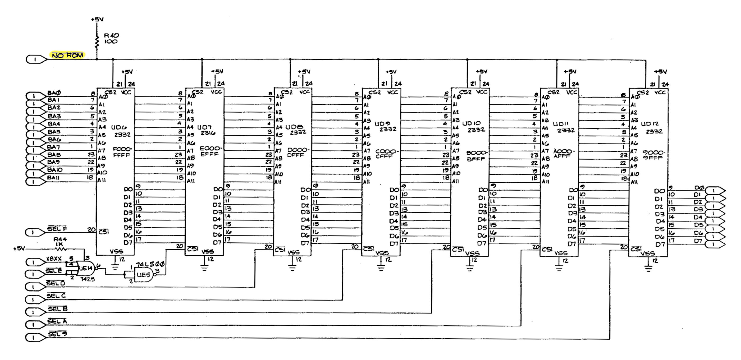
The ROMs in a CBM8032
Here, the 2nd chip celect CS2 (Pin21) is used. In the 2332, the chip selects are mask programmable (by the manufacturer). Here, it is active HIGH (while /CS1, Pin 20 is active LOW). The obsolete TI EPROMs TMS2532 fit in there without an adapter. Pin 21 is VPP, which usually has to be HIGH (5V) for normal operation. A low disables it. But the 2532 are hard to get and even harder to program, since the programming voltage is 25V and many EPROM programmers (like the TL886) are not capable of that.
This means, an adapter would be nice. The 27C64...27C512 have a chip select on Pin 22 and an Enable input on Pin 20. The Enable can be used as a 2nd chip select, but bot pins, mentioned before, are active LOW. That means, a (simple) inverter circuit is required.
This means, an adapter would be nice. The 27C64...27C512 have a chip select on Pin 22 and an Enable input on Pin 20. The Enable can be used as a 2nd chip select, but bot pins, mentioned before, are active LOW. That means, a (simple) inverter circuit is required.

Schematics of the CBM 2332 Adapter (click to enlagre)
The CBM 2332 EPROM Adapter does the inverting with a simple transistor circuit. The /NOROM signal is pretty static, anyways (= no speed requirements).
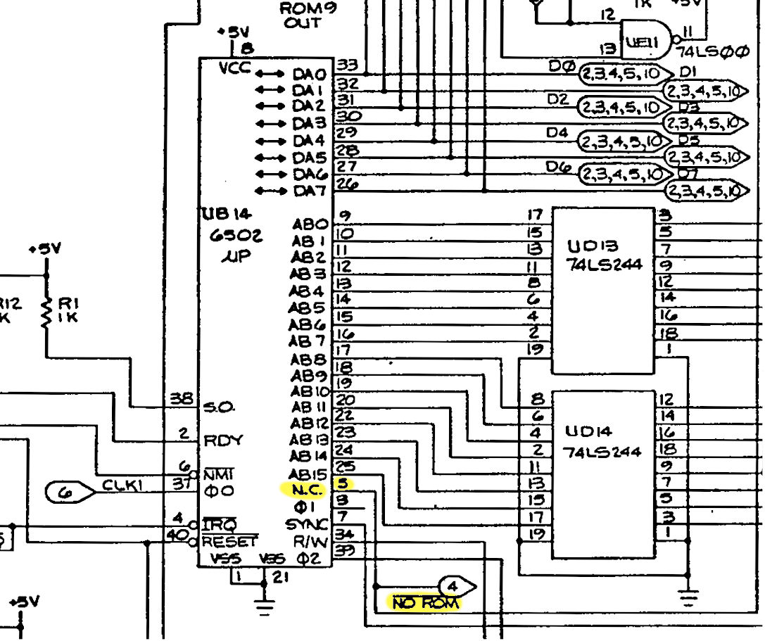
The CPU (6502) in a CBM8032
The /NOROM signal is connected to a pull-up resistor R40 and Pin 5 of the 6502. This pin is an N.C. (internally not connected) pin. Due to the said pull-up resistor /NOROM is permanently HIGH. The purpose is to switch off all ROMs (except the character ROM) and to attach a dedicated kernal (EPROM) in the diagnostic clip (this is not the same in the original PET) to start a diagnostic program instad of a normal boot.
Now back to the schematics of the CBM 2332 EPROM adapter: The fuction is straight forward, like my other EPROM adapters. The data bus and A0...A11 are connected both to the EPROM and the 2332 socket. The solder bridge JP3 and JP4 and D1 are for some trickery for a different project.
In case the /NOROM pin is not required, the solder bridge JP2 can be closed instead of placing R5, R6 and Q1.
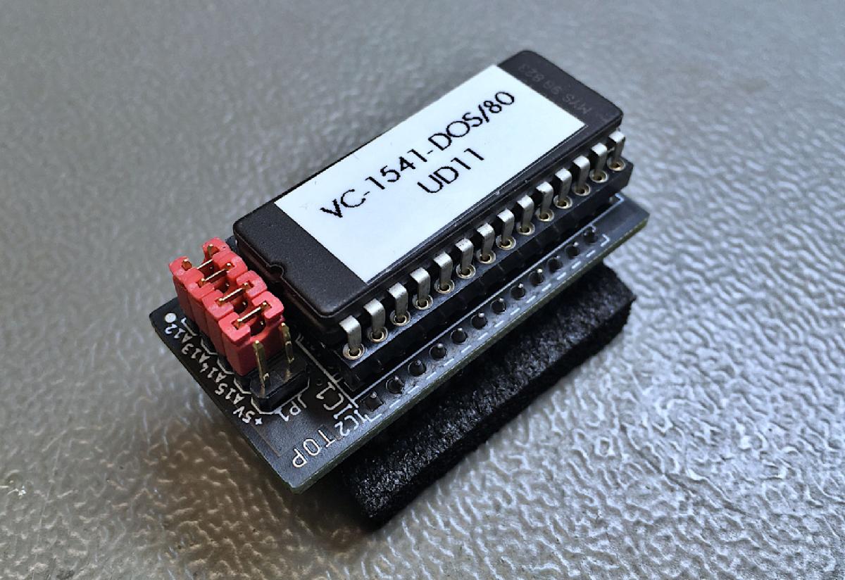
The EPROM's address bits A12...A15 are connected to the jumper JP1. This way, one of 16 images can be selected. A closed juumper/solder bridge represents a LOW level, and open jumper represents HIGH.
Now back to the schematics of the CBM 2332 EPROM adapter: The fuction is straight forward, like my other EPROM adapters. The data bus and A0...A11 are connected both to the EPROM and the 2332 socket. The solder bridge JP3 and JP4 and D1 are for some trickery for a different project.
In case the /NOROM pin is not required, the solder bridge JP2 can be closed instead of placing R5, R6 and Q1.
The EPROM's address bits A12...A15 are connected to the jumper JP1. This way, one of 16 images can be selected. A closed juumper/solder bridge represents a LOW level, and open jumper represents HIGH.
The CBM 2332 EPROM Adapter without the EPROM
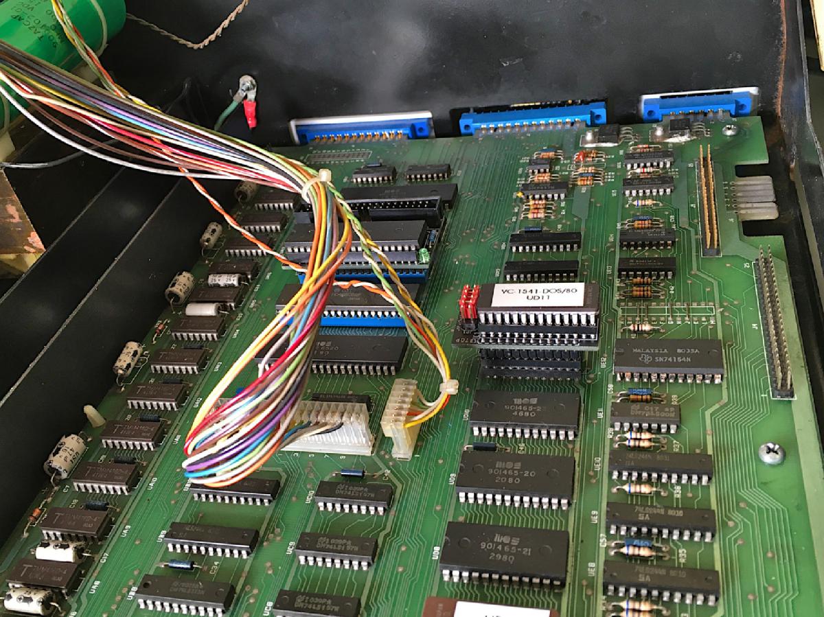
The CBM 2332 EPROM Adapter installed in UD11
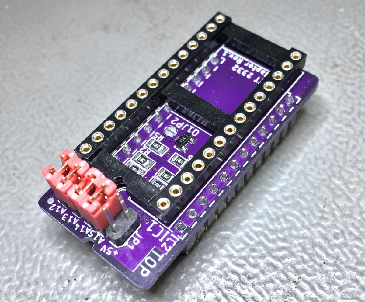
The CBM 2332 EPROM Adapter Rev. 1