


C64 WiFi Modem
Content
Introduction
Why Level Shifters?
Design
Getting the Firmware onto the NodeMCU
Using the Modem with other Commodore computers
VIC-20
The C64 WiFi Modem With The CBM8032
AT Commands
Repositories on Github
Introduction
Personally, I remember BBSes (and Fido Net) from the early 1990s, but I have been visiting them with a DOS PC and a 2400baud modem. I never used a modem on a Commodore C64. When I have found the instructions for building a WiFi modem for the C64, I was quite excited to build one.
Why Level Shifters?
I noticed, that the User Port was directly connected to a NodeMCUv3, which is an ESP8266 based processor module. The ESP8266 is a pretty wide spread WiFi enabled µController witha lot more processing power than the C64, so it is fun to connect both. The head scratcher is the ESP8266 is running from 3.3V with the respective logiv levels and the 6526 CIA is a 5V device with TTL logic levels.
Reading the logic levels from the ESP8266 should not be a problem, since every voltage above 2.4V is a valid HIGH level. Driving an input of the ESP8266 might be a problem, though...
Introduction
Why Level Shifters?
Design
Getting the Firmware onto the NodeMCU
Using the Modem with other Commodore computers
VIC-20
The C64 WiFi Modem With The CBM8032
AT Commands
Repositories on Github
Introduction
Personally, I remember BBSes (and Fido Net) from the early 1990s, but I have been visiting them with a DOS PC and a 2400baud modem. I never used a modem on a Commodore C64. When I have found the instructions for building a WiFi modem for the C64, I was quite excited to build one.
Why Level Shifters?
I noticed, that the User Port was directly connected to a NodeMCUv3, which is an ESP8266 based processor module. The ESP8266 is a pretty wide spread WiFi enabled µController witha lot more processing power than the C64, so it is fun to connect both. The head scratcher is the ESP8266 is running from 3.3V with the respective logiv levels and the 6526 CIA is a 5V device with TTL logic levels.
Reading the logic levels from the ESP8266 should not be a problem, since every voltage above 2.4V is a valid HIGH level. Driving an input of the ESP8266 might be a problem, though...
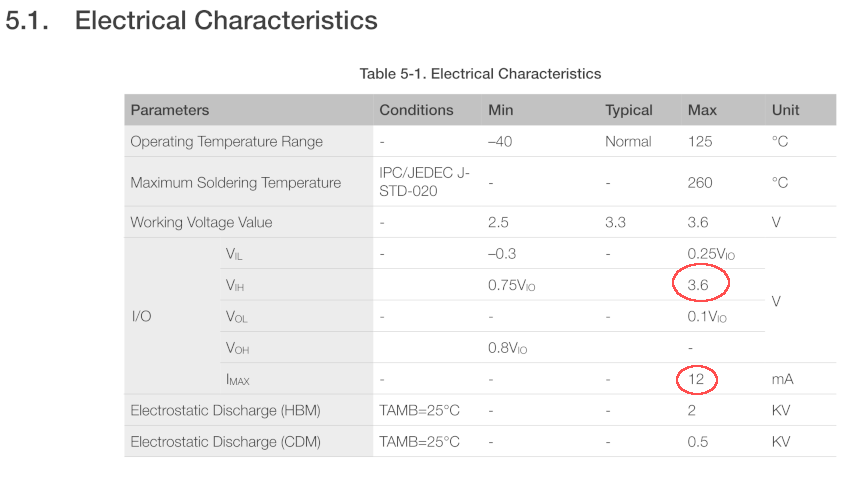
The maximum input voltage is clearly 3.6V. There are rumors, that the ESP8266 is "5V tolerant", but finally, I believe the official data sheet and not a rumor. Anyways... the C64 WiFi modems out there seem to work, right? Yes, but...
The CIA has pretty weak outputs. The data sheet says, it is 1000µA maximum current sourcing capaility at HIGH level. Maybe even only 200µA.
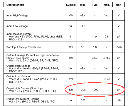
Excerpt from the MOS 6526 data sheet
I assume, the ESP8266 I/O pins have some sort of protection circuit and the weak output current of the CIA will not destroy this pin protection. The question is: Do you really want to apply that much stress (maximum current) to the I/O pins of a chip from the early 1980s?
I decided, I don't want it. This is the reason for the level shifters in my WiFi modem design.
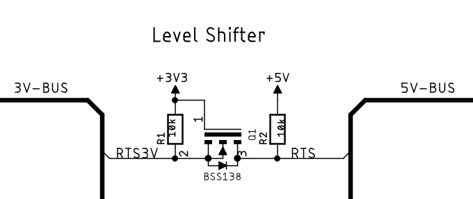
Level shifter circuit
The level shifter circuit is pretty simple and it is bi-directional. AFAIK, it was introduced by Philips for I²C bus level shifting in mixed logic voltage systems. It can be found on those typical "Level shifter for Arduino" modules, which are avaliable on ebay, AliExpress etc.
Design
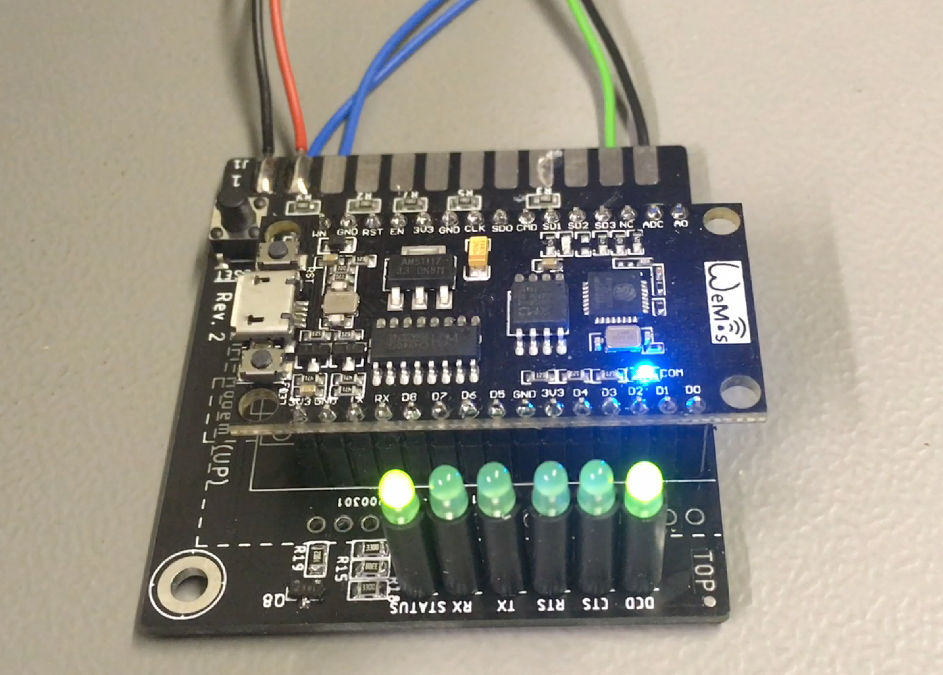
I also thought about features, that I would want to see on my design. That is definitely blinken lights! The (analog) modems back in the last millenium had plenty status LEDs, so I incorporated them in my design. And a reset button is alays a useful thing, since Commodore had forgotten to install one in the C64.
Design
I also thought about features, that I would want to see on my design. That is definitely blinken lights! The (analog) modems back in the last millenium had plenty status LEDs, so I incorporated them in my design. And a reset button is alays a useful thing, since Commodore had forgotten to install one in the C64.
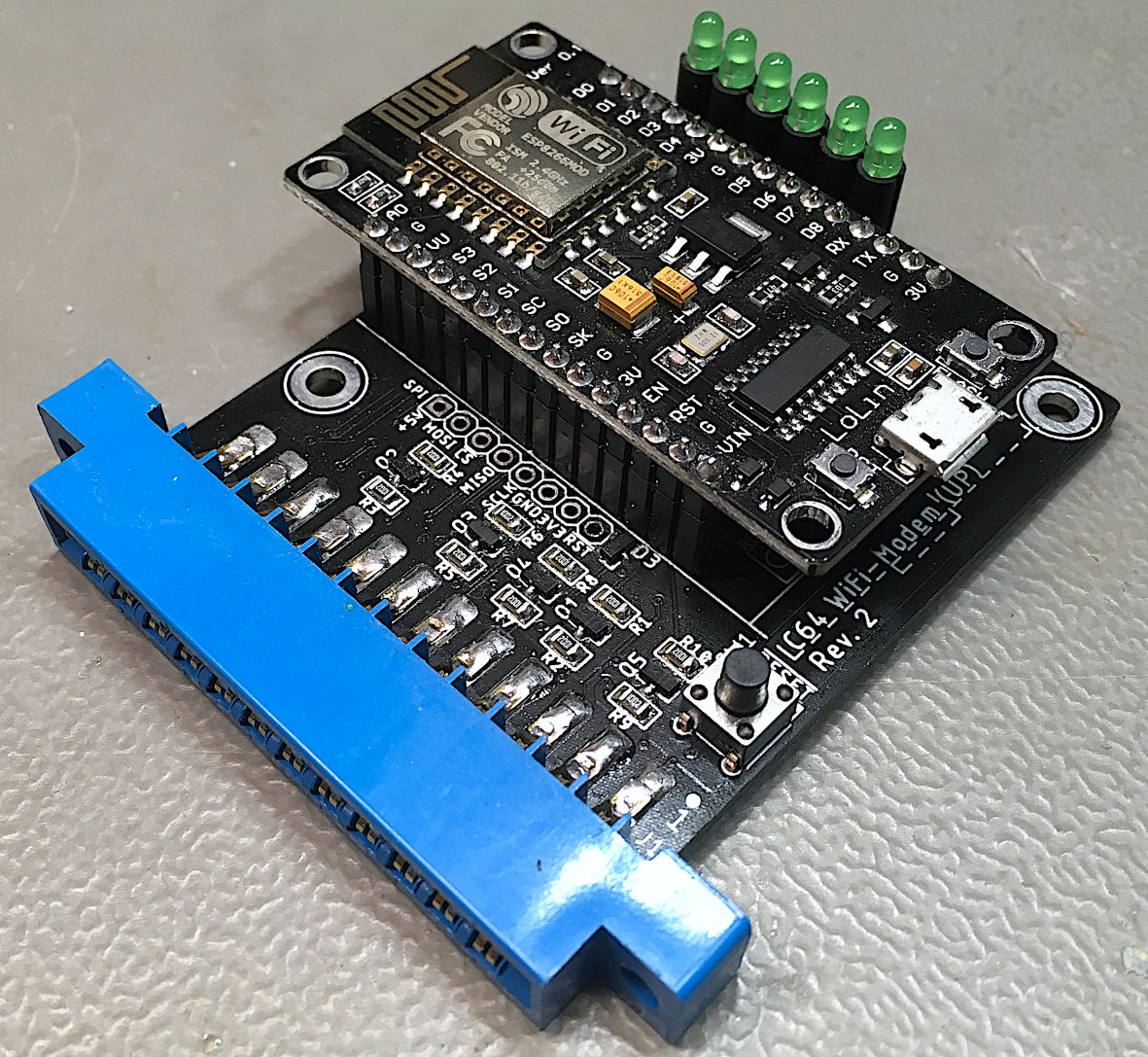
C64 WiFi modem Rev. 2 with the wide NodeMCUv3
There are two sorts of NodeMCU v3 available and since one always gets the wrong one (including me) and they are both named the same, the Rev. 2 board allows to install both kind modules. The PCB measures are different, so the 3D printed case was re-designed for the Rev. 2.
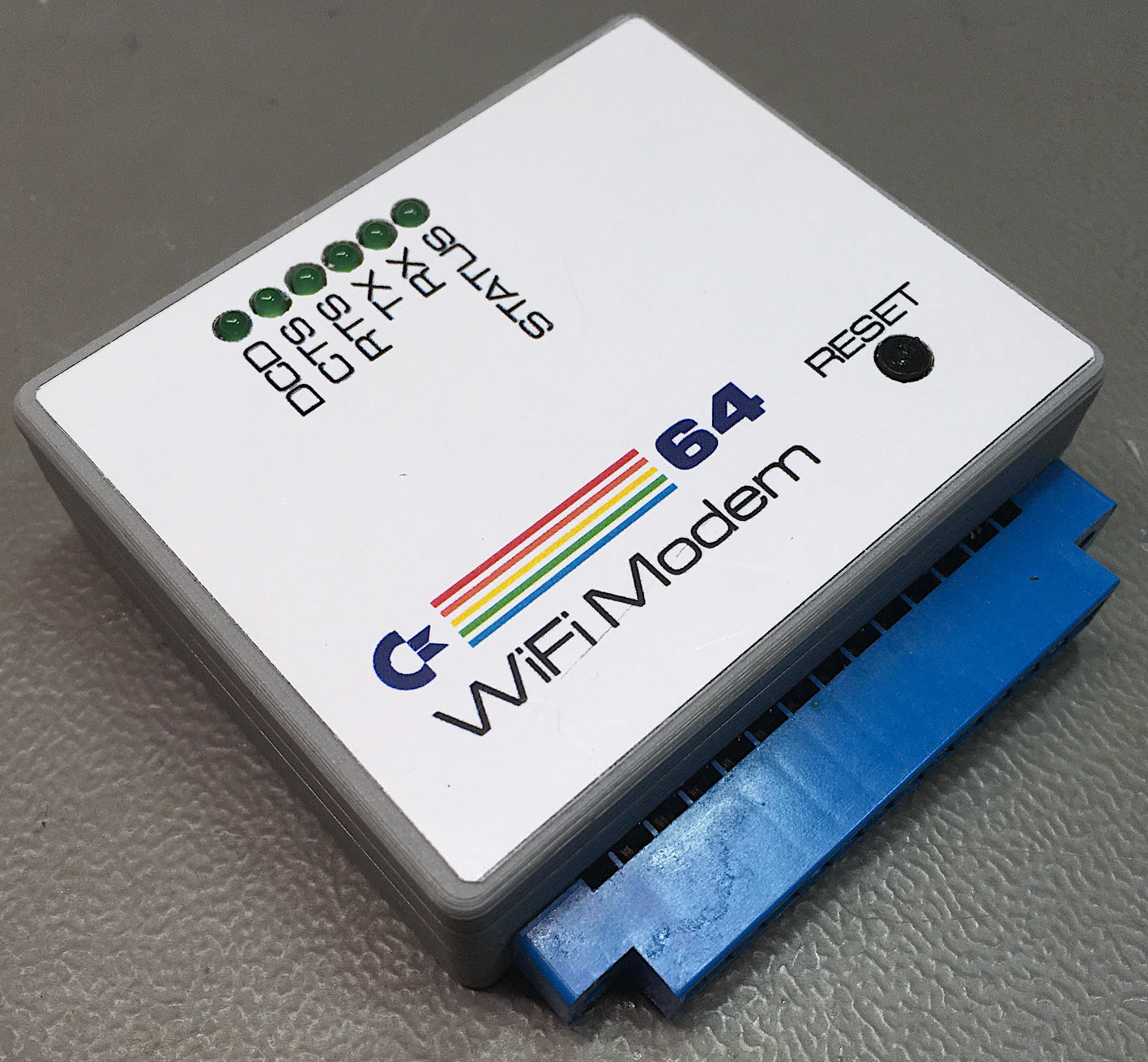
C64 WiFi Modem in a 3D printed case
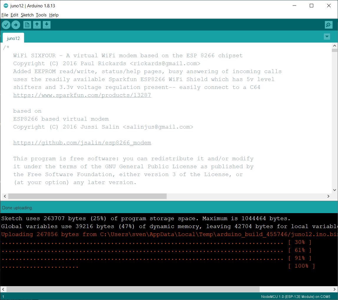
Getting the Firmware onto the NodeMCU
The 1200baud instructions suggest two methods of getting teh firmware onto the NodeMCU. For me, only the way via the Arduino IDE worked out and nobody, I had talked to, said, the loader worked for them.
All that is required is:
● a micro-USB B cable (like the charging cable for a smart phone
● the Arduino IDE
● The firmware(juno12.ino)
● select the right port after connecting the NodeMCUv3
● select the proper board type (NodeMCU 1.0 (ESP-12E Module))
● click upload (Sketch -> Upload or Ctrl+U)
The firmware will then be compiled and finally uploaded. Probably, the LED on the NodeMCU is switched on now.
For connecting the C64 to BBSes, you need a terminal program. I have tested CCGMS 2017 with success (while I did not have success with CCGSM 2021).
For configuring the modem and CCGMS and the modem, follow the instructions on 1200baud.worldpress.com
Notes:
● always select the Baudrate the Modem is configured to. By default (after the firmware installation), it is 300 baud.
● Make sure, you are in ASCII mode of the terminal program, before you enter the ssid and the password. Otherwise, lower care and upper case will be messed up and nothing works.
● do not forget to save the settings in the wifi modem with at&w, other than that, the setting will be lost after a power cycle.
In CCGSM, it is no problem to operate the modem with a minimum knowledge of the AT instruction. AT is the prefix of every modem instruction.
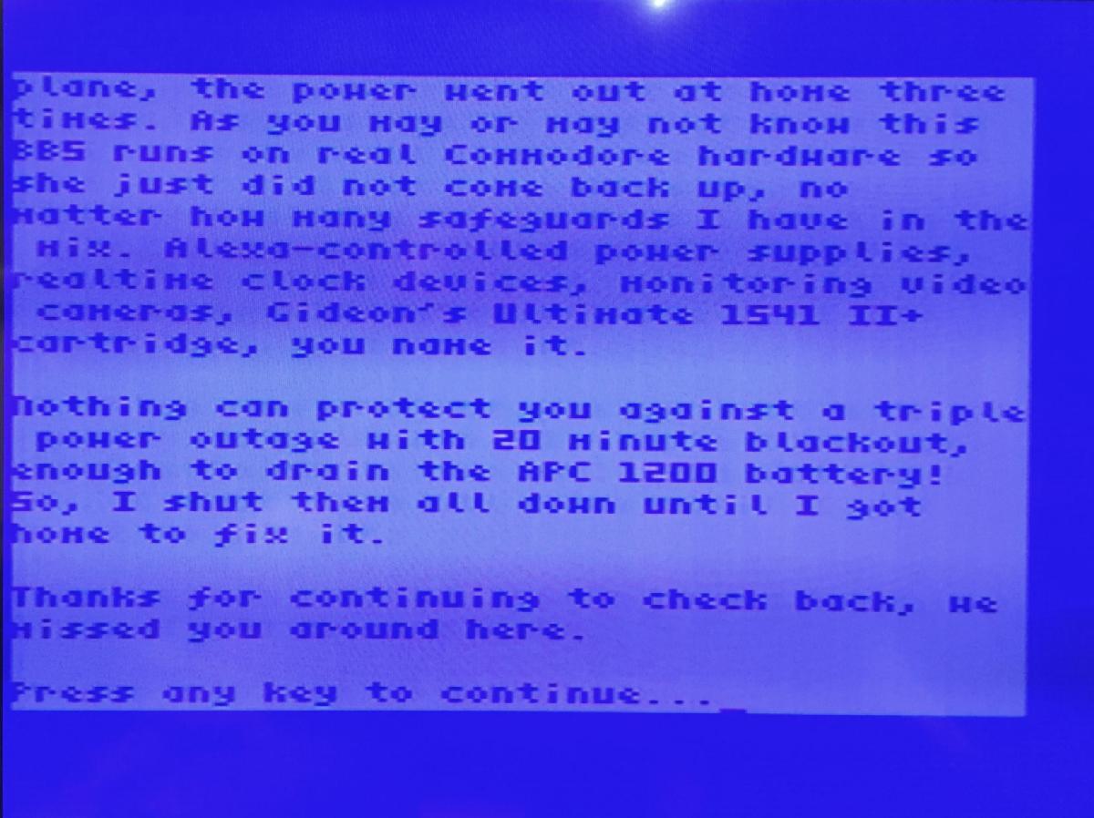
To get a connect message from the modem just hit the RETURN key. The modem's welcome message will be displayed (in case the baud rate is selected properly) and it will try to connect to your WiFi network.
Sometimes the connection does not work out (for whatever reason). Try to disconnect with atc0 and reconnedt with atc1.
A list of BBSes for the C64 can be found here. Hint: 13th floor BBS has the most connections, because it is top of the list. Try other BBSes as well.
Using the Modem with other Commodore computers
I could of course not resist to connect the C64 WiFi modem to my other Commodore computers.
VIC-20
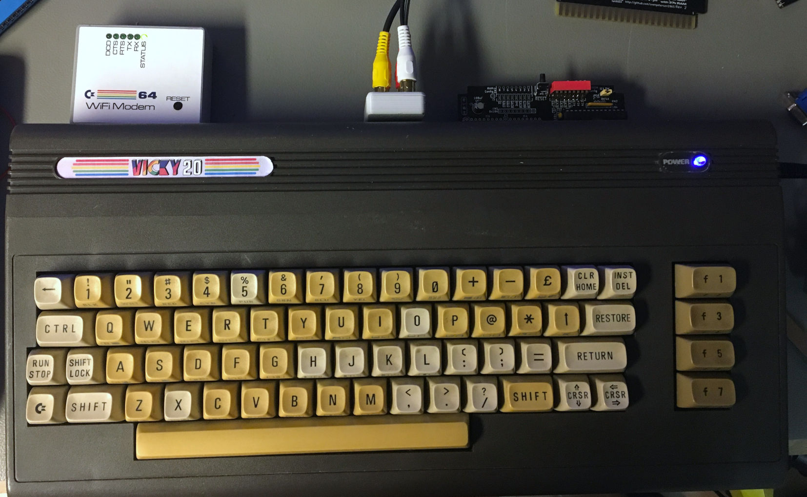
The C64 Wifi Modem with the VickyTwenty (A VIC-20 clone).
For the VIC-20, it just requires a proper terminal software and you are set. I have tried out VICTERM4.0 from zimmers.net. This is a cartridge sioftware, which I have installed on the Hyper Expander.
VICTERM 4.0 in the original NTSC mode (on my PAL VIC-20)
It shows, that the software is for NTSC. With PAL, the "active area" of the screen is sticking to the left side of the display. I have hacked the firmware to make a PAL version.
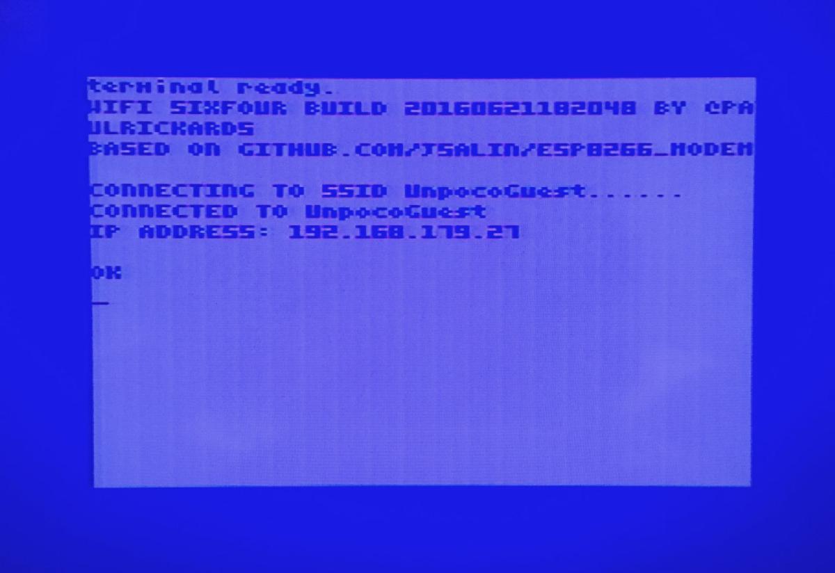
VICTERM 4.0 (PAL hack) in 40 column mode, showing the modem welcome message
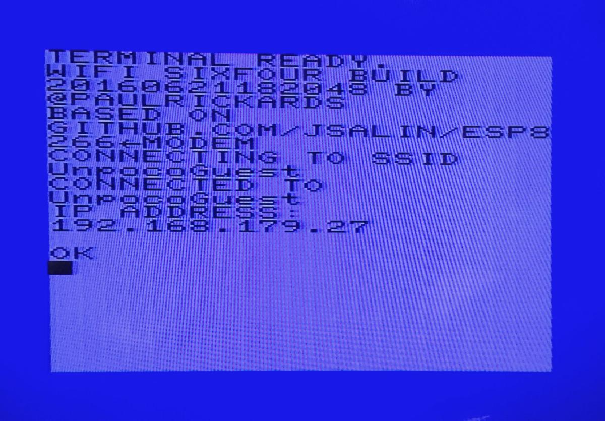
VICTERM 4.0 (PAL hack) in 22 column mode, showing the modem welcome message
VICTERM is a quite simple terminal program, which does not provide dialing lists, etc. It is required to know more about the AT comamnds than with CCGMS for the C64.
Please find the patched PAL Version of VIC Term here.
The C64 WiFi Modem With The CBM8032
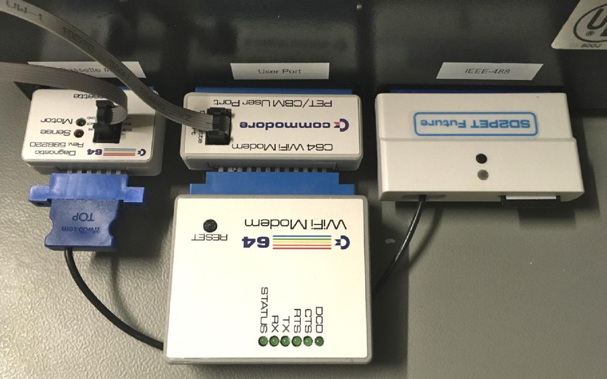
The PET and CBM user ports does not provide a +5V pin for supplying the C64 Modem. The pinout for the I/O-Pins is equal, though. First, I have built myself a hacked version of the WiFi modem, that has teh user port connector attached to a cable, tapping the cassette port for the +5V.
Hacked C64 WiFi modem for the CBM8032
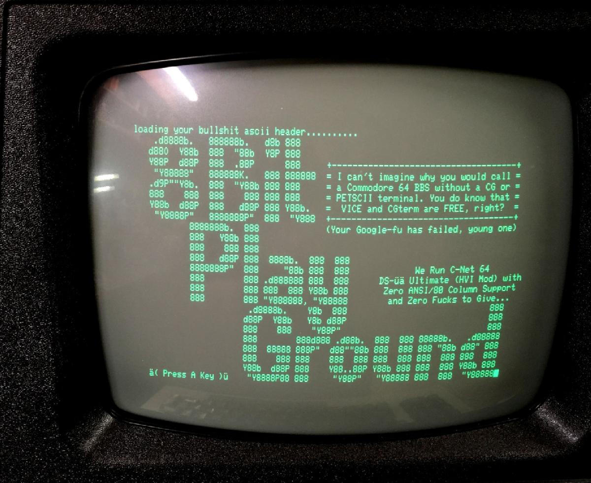
8Bit Play Ground BBS on the CBM8032
Since this worked out well, I decided to build an adapter for the WiFi modem, that connects to the Cassette Dongle of my C64 Diagnostic Harness.
AT Commands
AT is the prefix of the commands, that can be sent to the modem with the terminal program.
Here is a list of those, implemented in the NodeMCU firmware:
Query most comands followed by '?'
Please refer to: https://github.com/jsalin/esp8266_modem
Repositories on Github
My projects are open source hardware an can be found on github:
● C64 WiFi Modem
● C64 WiFi Modem Adapter for PET/CBM