


Datassette Encoding
Content
Preface
Bit Encoding
Byte Encoding
Data Block Encoding
The Header Block
Header Type
Header Type And Secondary Address
The Listening Contraption
Sources
Acknowledgements
Preface
A couple of days ago, I wanted to dig a bit deeper into the Datassette. I have not been using it in decades and I had some in my stach. They came as a by-catch. Back in the day, I was only used the Datassette until I got a floppy disk drive (1541) for my VIC-20.
Anyway, understanding the way the Datassette works is a good thing. I was looking up "Datassette" on c64-wiki.de and found, that there was nothing about how everything is encoded. So I decided to write something about and got out the Data Becker book "Das Cassettenbuch zu Commodore 64 und VC-20", but that was very incomplete. Nick Hampshire's "The PET Revealed" was a bit more precise, but partly faulty and also incomplete.
The best would be to ask somebody, who had made a tape emulator for hints. I had been in contact with Marcel Timm before, who had made the CBM Tape Pi and he has sent me a link to his transcript, which was enlightening.
There were still a few things that I did not understand, especially, since I had read some incorrect information before. So I have built a contraption, that lets me listen to the recording on the cassettes. A scope is a good thing to find out about the bits, but the ear is the ultimate tool to understand the over-all structure of a data file.
Bit Encoding
Many computers of the home computer era used FSK (Frequency-shift keying) to encode the "1" and "0" on tape, using different frequencies for each - e.g. the Kansas City standard. The Commodore Datassette is making use of a pulse length encoding, which "The PET Revealed" calls superior to FSK.
There are three sorts of pulses, that are made use of:
● a short 176µs pulse (2840 Hz)
● a medium 256µs pulse (1953 Hz)
● a long 336µs pulse (1488 Hz)
Actually, the pulses occur as one full period of the respective frequency, so a short pulse is 176µs of HIGH and 176µs of LOW level etc.
The bit values and the required markers are encoded with combinations of two of these pulse periodes.
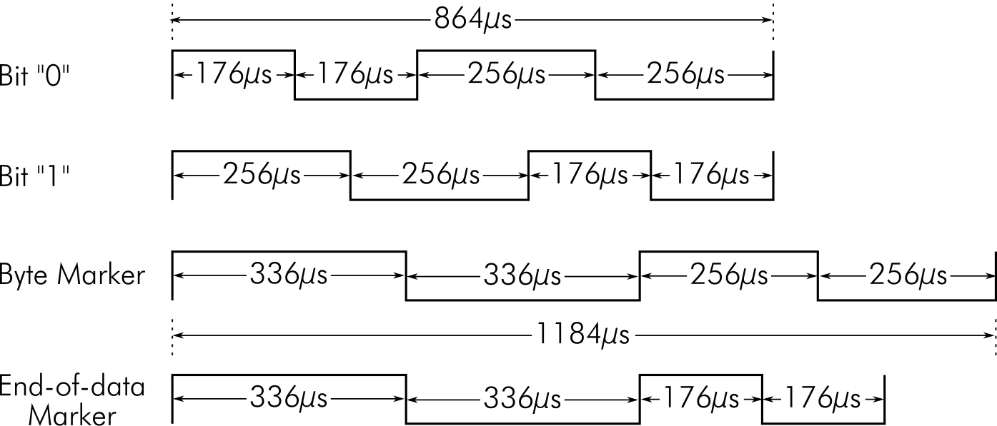
Encoding of the bit values and markers (NTSC)
● The bit value "0" is encoded as a short pulse period followed by a medium pulse period
● The bit value "1" is encoded as a medium pulse period followed by short pulse period
● The byte marker is encoded as a long pulse period followed by a medium pulse period
● The end-of-data marker is encoded as a long pulse period followed by a short pulse period
Bit "0" on a PAL system. A short and a medium period
Bit "1" on a PAL system. A medium and a short period
With the scope, I found out, that the pulse durations vary between NTSC and PAL machines. Since the NTSC clock is approximately 3.8% faster (1.0227273 MHz for NTSC vs. 0.9852486 MHz for PAL), the PAL pulses are 3.8% longer. However, it is no problem to exchange cassettes between NTSC and PAL C64s. The speed of the tape motor varies, too, so there are synchronization algorithms integrated into the data decoding.
The different PAL pulse lengths and frequencies are:
● a short 182.7µs pulse (2737 Hz)
● a medium 265.7µs pulse (1882Hz)
● a long 348.8µs pulse (1434 Hz)
With a (decent) oscilloscope, it is possible to trigger on certain pulse durations. The byte marker contains the "long" pulse, so the first byte marker in the tape recording can be found with little effort. When writing the files, the signals are generated by the computer, so motor (tape) speed fluctuations do not produce a jitter and the signals are closer the ideal specification.
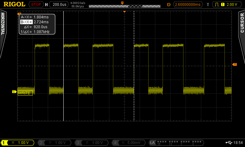
A byte marker on an NTSC system while recording a file. Measured duration: 1.200ms
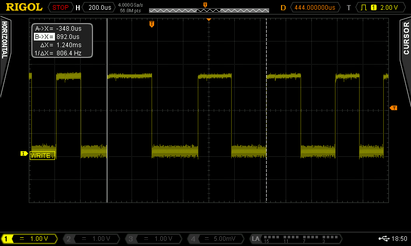
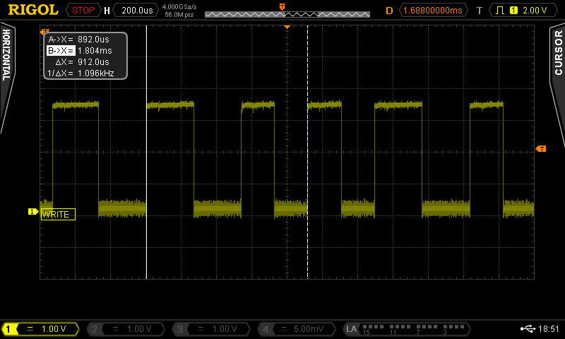
A byte marker on a PAL system while recording a file: Measured duration: 1.240ms
The calculated duration of a byte marker on an NTSC machine is 1184µs and on a PAL system, it is 1229µs. The oscilloscope screen shots come very close to these ideal values.
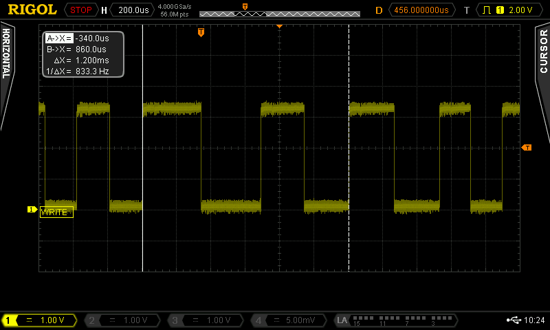
The read signal is inverted to the write signal (and slightly phase shifted, when showing both on the scope simultaneously).
The read signal is inverted to the write signal (and slightly phase shifted, when showing both on the scope simultaneously).
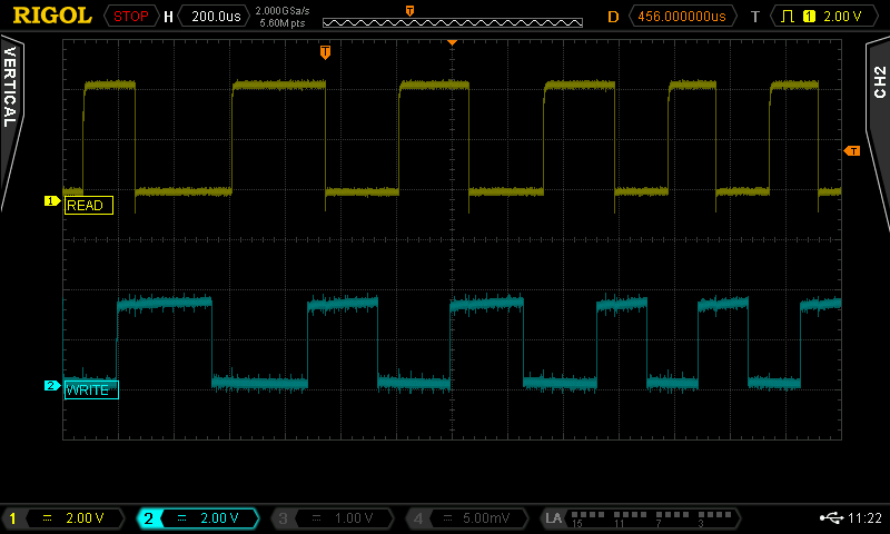
This screen shot shows the synchronization leader on READ and WRITE on an NTSC system
While the pulse width is measured between the rising edges for the write signal, it is measured between the falling edges for the read signal.
Byte Encoding
The byte marker indicates the start of a byte. The bits are recorded with the least significant bit (LSB) first and a parity bit (odd parity) followf the most significant bit (MSB).
Byte Encoding
The byte marker indicates the start of a byte. The bits are recorded with the least significant bit (LSB) first and a parity bit (odd parity) followf the most significant bit (MSB).
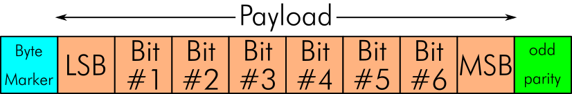
Datassette byte encoding
"Odd parity" means that the number of "1s" in the data bits plus the parity bit is odd. E.g., for 00100010 (even number of 1s) the parity bit would be 1, for 00000111 (odd number of 1s) the parity bit would be 0. This is generated by sequentially XORing a "1" and all 8 payload bits.
Each byte has a recorded duration of 8.96ms.
Data Block Encoding
The 192 bytes of payload are stored twice in one block. Beside the checksum, this is for detecting data integrity problems due to auto dropouts.
Each data block starts with a synchronization leader of short pulses (2840 Hz for NTSC) . This is either 10 seconds for the first block or 2 seconds for every other block. The leader provides time for the tape motor to reach the correct speed. Also the kernal calculates a speed correction factor during this time, since tape speed might vary for different motors. For this is the reason, despite the different PAL and NTSC clock frequencies, there is no issue with swapping tapes between systems.
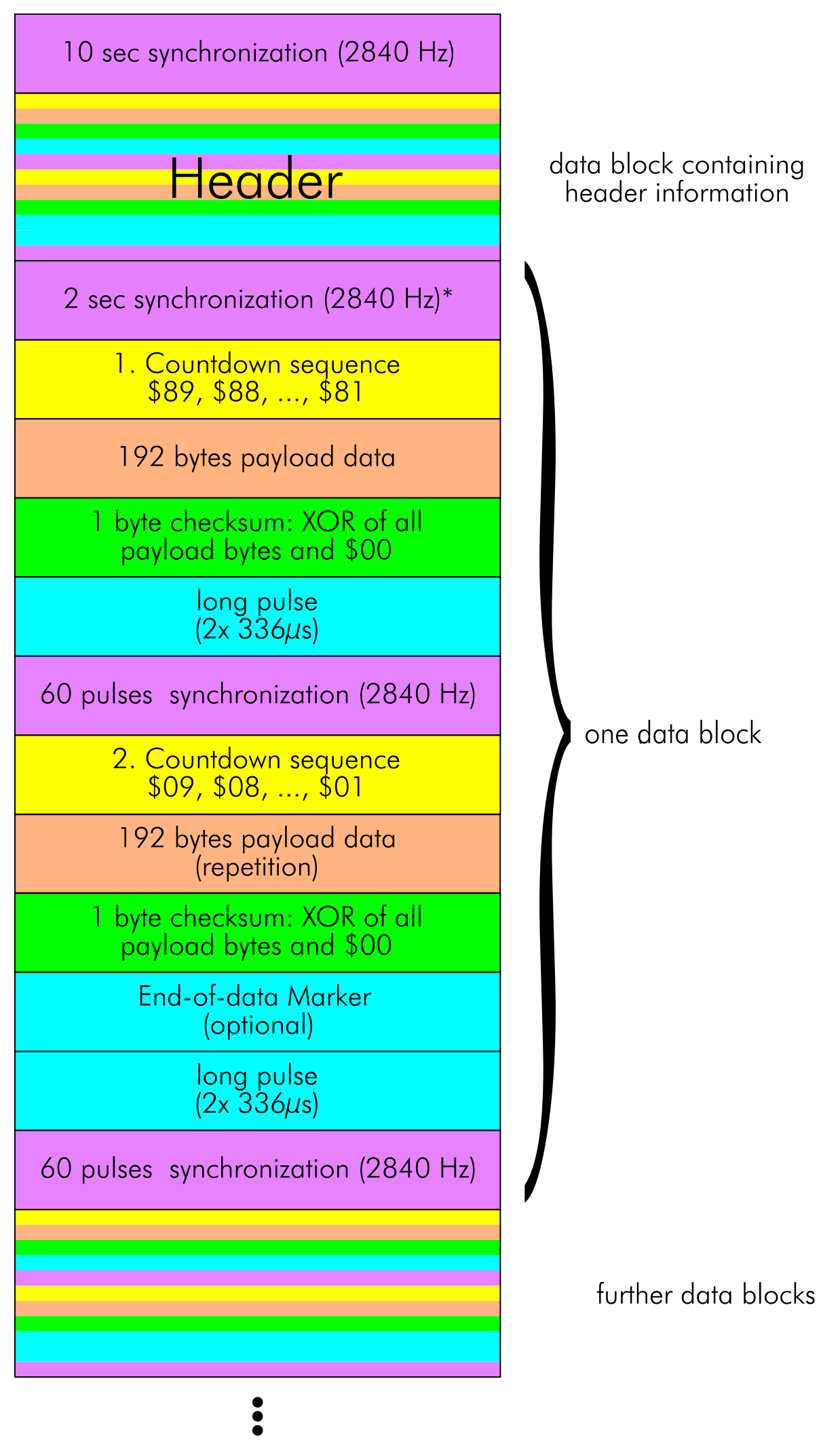
Structure of a file and the data blocks, that it is made from
Each block of payload data is preceded by a countdown byte sequence. The countdown has the MSB set for the first copy of the payload data, counting from $89 to $81 and cleared for the 2nd copy of the payload data, counting from $09 to $01.
Each data block is followed by a one-byte checksum. It is calculated by sequentially XORing $00 and all payload bytes.
The inter-record gaps start with a long pulse period, followed by 60 short pulse periods (2840 Hz).
The end-of-data marker is an optional symbol, marking the last data block.
The Header Block
The header block is the first data block in a file file and is exactly 192 bytes in length. The header payload consists of the file type, the start and end address (used for certain header types) and the file name.
In case the file name is shorter than 16 characters, it is padded with spaces (ASCII: $20). The bytes 22 - 192 are usually filled with $20. In case a file name is used, that is longer than 16 bytes, only the first 16 characters are displayed in the FOUND message, all other characters are still valid, but will not be displayed in the found message. They can be accessed with the PEEK instruction, though.
Header Type
Header Type $01
This header type denotes relocatable programs. In general, these are BASIC programs which do not necessarily require to be located at specific addresses. These programs are loaded at the start of BASIC RAM.
Header Type $02
This type denotes a data block of a sequential (ASCII) file. The bytes 1-192 (which is 191 bytes) contain the payload data.This block does not make use of the start and end address.
Header Type $03
This type denotes non-relocatable programs - usually those are machine language programs or programs with a machine language section. They require to be loaded to a certain start address.
Header Type $04
This type denotes the header of an ASCII file. Besides the header type, the payload of this block contains the file name.
Header Type $05
This type denotes an End-of-tape block. In case the EOT is reached, before a header with the desired file name is reached, a "DEVICE NOT PRESENT ERROR" is reported.
Header Type and Secondary Address
The secondary address, which is used, when a file is saved or opened for writing influences the header type, that is recorded on tape.
Programs
Loading
Saving
Opening an ASCII file
The Listening Contraption
The scope might be useful, but without being abble to decode the complete data stream (my scope does do serial, I²C and all that stuff), it is hard to trigger/find anything, but the first byte marker.
For an overall understanding and verification of the file structure, the ear is a pretty good instrument. It is of course easy to hear the single frequency leads. It is also possible to distinguish a "random byte pattern" (like the program bytes) from the space padding of the file name (which is a lot of $20 in a row). You also don't miss the short (60 pulses) synchronization pattern between each copy of the payload data.
The Cassette Dongle of my diagnostic harnesses serves for tapping the Datassette signals. The wiring itself consists of a 10k potentiometer, two DuPont connectors for the pins of the Cassette Dongle and a (female) RCA connector to connect to an audio channel of my HDMI converter.
The potentiometer is set to a pretty low volume and it could be replaced with fix resistors (1k5 between tap and GND for the output and 8k2 between input and tap or 2k2 and 10k, it does not need to be very accurate).
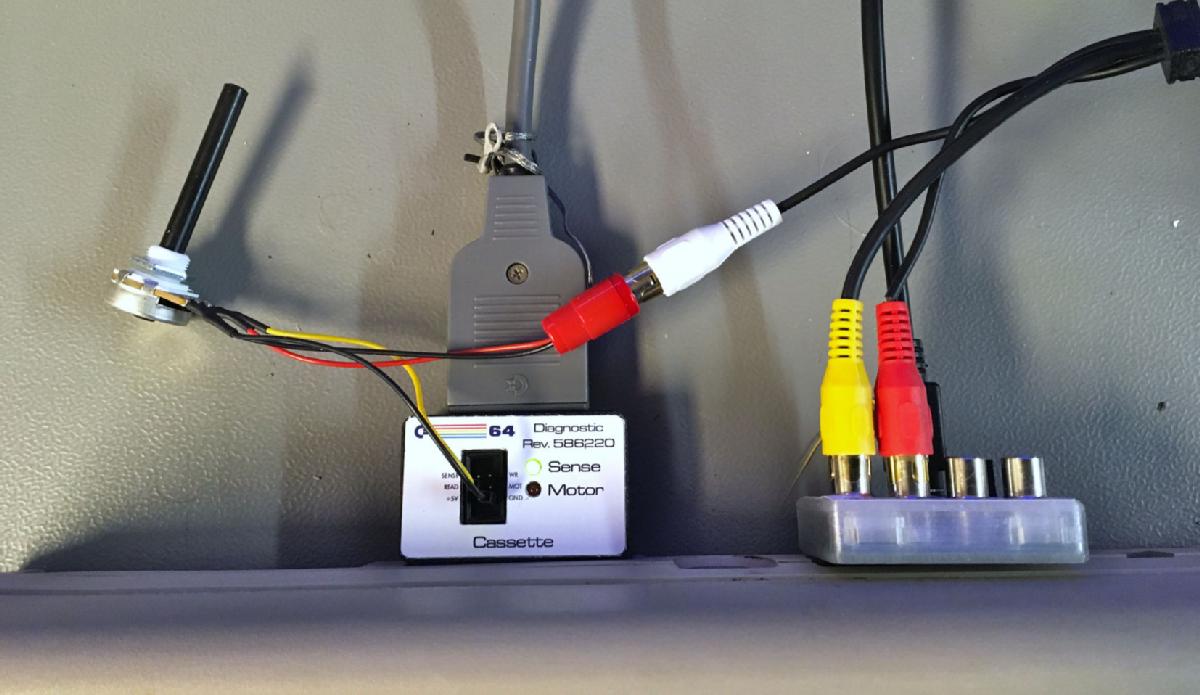
Datassette Listening Contraption

Schematics of the listening contraption
Resources
● Nick Hampshire: "The PET Revealed", 1980 (English), Page 135-142
● Dirk Paulissen: "Das Cassettenbuch zu Commodore 64 und VC-20", 1984; Data Becker (German), Page 52f.
● Marcel Timm: "Ordered Tape to CBM content" (English)
● Said Baloui et al.: "Das neue Commodore 64 Intern Buch", 1990; Data Becker (German), Page 420f.
● github - ikorb: "tapecart/main.c" (source code)
● Dan Heeb: "Compute!'s VIC-20 and Commodore 64 tool kit: Kernal", 1985; COMPUTE! Publication, Inc. (English) Page 269ff.
● Simon’s Mostly Reliable Guide to the Commodore Tape Format (English)
C64tapes.org is unfortunately down, but it can still be found at archive.org.
● CBM ROM Loader
● Analyzing C64 tape loaders
Acknowledgments
I would like to thank everybody on Twitter and Facebook for their hints about this topc.
Marcel Timm for discussing the topic and showing me his great essay about the formate.
Mike Doornbos for introducing me to "Compute!'s VIC-20 and Commodore 64 tool kit: Kernal", this is a truely great book.
Peter Edwards for all his input and especially for editing this essay.
[[work in progress]]