


CBM 1541 Adapter
Introduction
Reconstructing (=guessing) the Hardware
Analyzing the EPROM Binaries
The Instructions
Testing
Note
Github Repository
Introduction
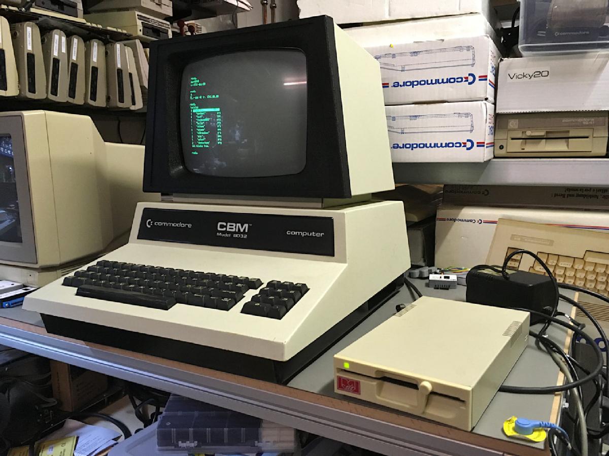
Inside my CBM8032, that I had repaired, I have found three special ROMs. One was labeled "VC-1541-DOS/80". I assumed, that this might be working with a User Port adapter for the 1541 (IEC-Bus). What an exciting thing!
It was a 2532 type EPROM sitting in the UD11 socket, which is good for software at $A000-$AFFF. I could not read it with my TL866II+ programmer, since there was no such tape, so I have built an adapter to read it as a 2764 EPROM (since I do not intend to write it, no problem). Later, I have ripped the EPROM content with the BackBit Chip tester and compared both files. Both were identical, so the adapter worked and the chip tester, too.
This is the eprom image: UD11_1541_80_A_2532.zip
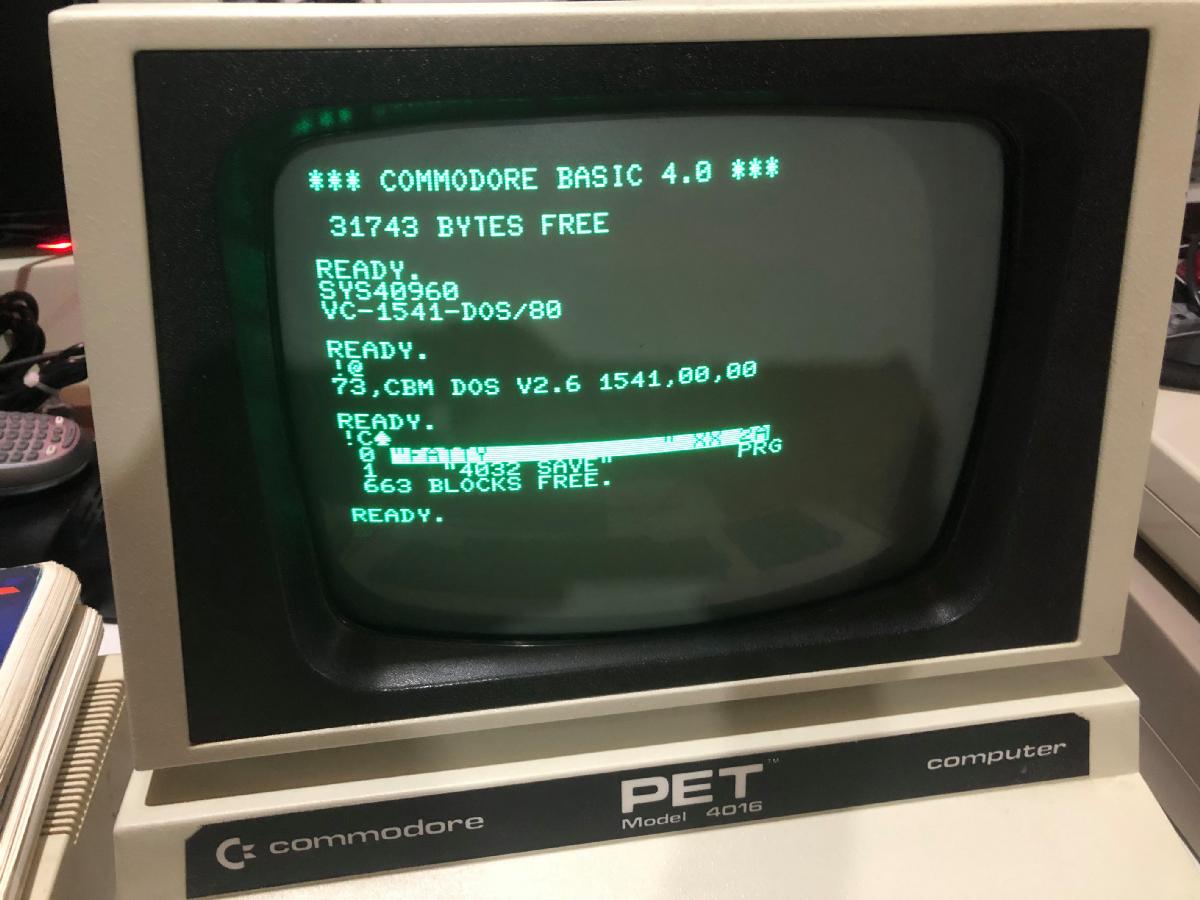
I have sure tried out, what happend, when I started it. Since the software is situated at $A000 ..., I tried SYS40960.
Reconstructing (=guessing) the Hardware
Analyzing the EPROM Binaries
The Instructions
Testing
Note
Github Repository
Introduction
Inside my CBM8032, that I had repaired, I have found three special ROMs. One was labeled "VC-1541-DOS/80". I assumed, that this might be working with a User Port adapter for the 1541 (IEC-Bus). What an exciting thing!
It was a 2532 type EPROM sitting in the UD11 socket, which is good for software at $A000-$AFFF. I could not read it with my TL866II+ programmer, since there was no such tape, so I have built an adapter to read it as a 2764 EPROM (since I do not intend to write it, no problem). Later, I have ripped the EPROM content with the BackBit Chip tester and compared both files. Both were identical, so the adapter worked and the chip tester, too.
This is the eprom image: UD11_1541_80_A_2532.zip
I have sure tried out, what happend, when I started it. Since the software is situated at $A000 ..., I tried SYS40960.
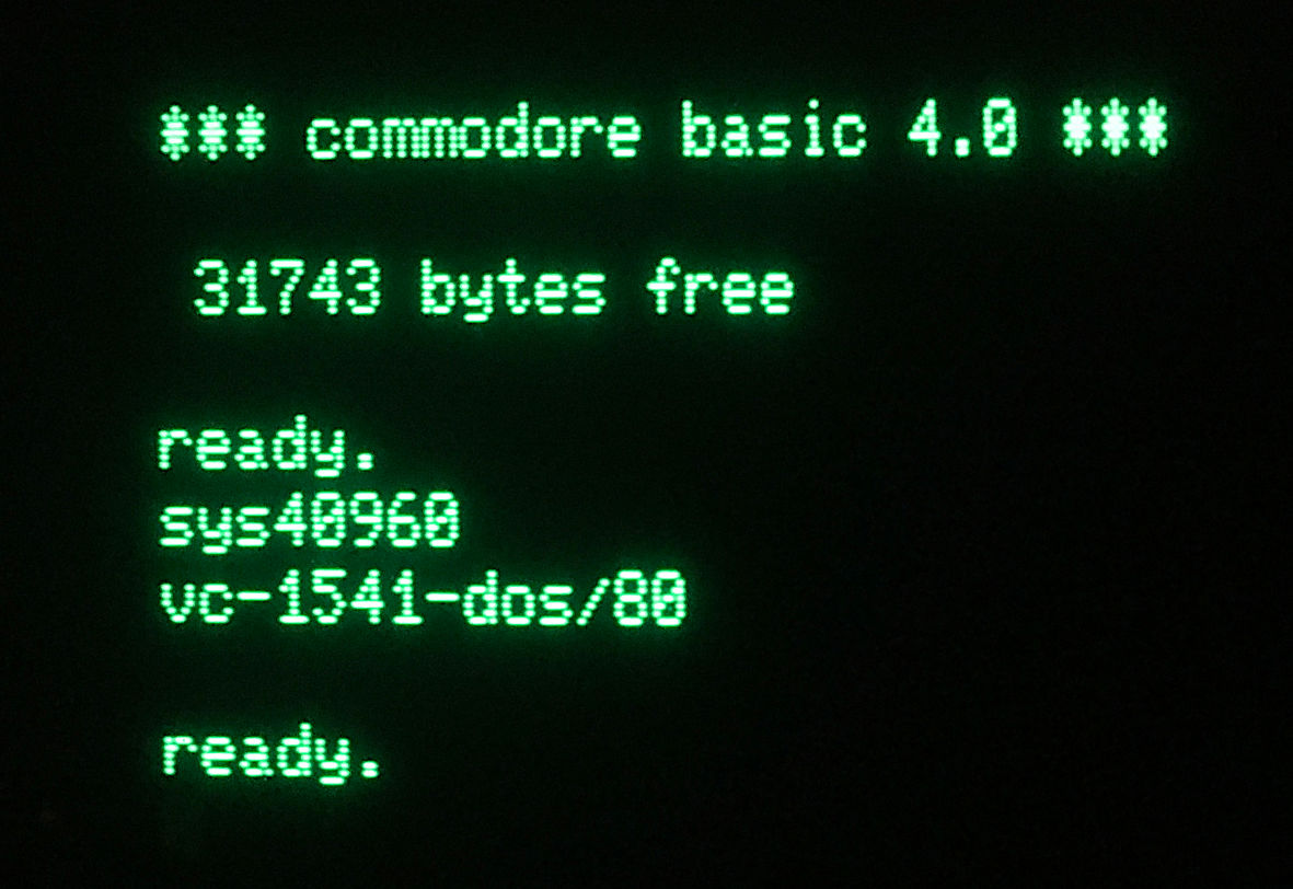
And voila... the software started, reporting vc-1541-dos/80. The VC shows, that it is a German software. I was digging slightly deeper and viewed teh BIN file in a HEX editor (HxD).

This is a copyright notice: "(C) G MUTZ (84)". I could not find anything out about G. Mutz or VC-1541-DOS, yet.
Unfortunately, I don't have any old magazines to search for the product or the guy.
Reconstructing (=guessing) the Hardware
In August 2021, I was contacted by HofMar (Martin) from forum64.de. He said, it looked like some C64 kernal code fragments (between $A3B9 and $A57F) and suggested to map the IEC signals to the same port bits like the C64. Of course, some driver circuits are required.
The port bits in the C64 are:
This resulted in the following schematics for the adapter hardware:

Click to enlarge
I decided to put the port pins on a pin header, so I could also try other combinations, in case this does not work. I also decided to add 74LS04 inverters as receivers. This offered me the possiblity to invert both signals with jumpers (if required).
I also added a 6pin box connector and a barrel connector for providing the supply voltage (unfortunately, the PET/CBM User Port does not provide 5V).
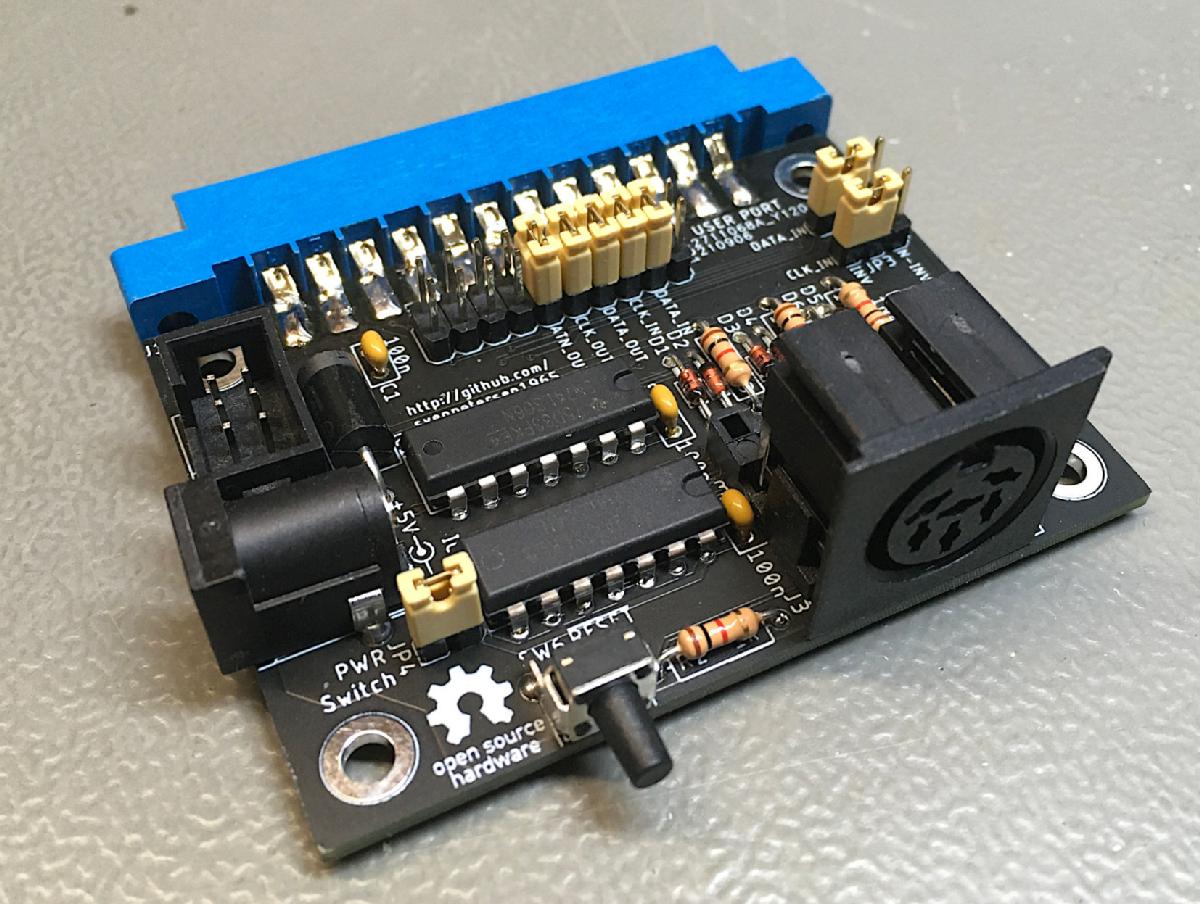
CBM 1541 Adapter Rev. 1
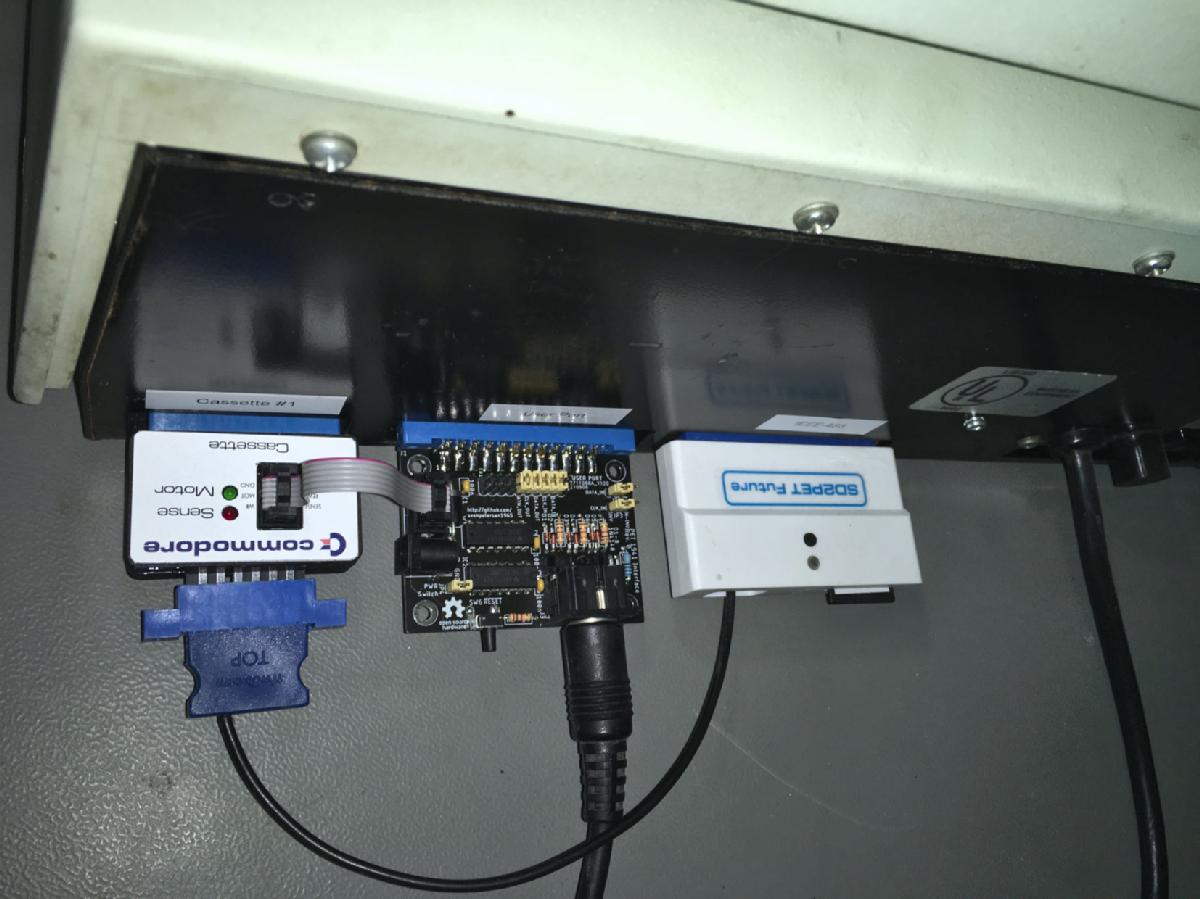
Installation with the Cassette port dongle for supplying +5V
Analyzing the EPROM Binaries
Since the normal instructions did not access anything, I had to look through the disassembly of the code, that I have found in the EPROM. First, I had to look for the user port accesses, which were found pretty soon. The routines were adapted codes from the C64 kernal.
The most important were:
Find the disassembly of the bin here.
First, there is the initialisation routine for the PIA:
$A390: RESET_VIA
$A390: A9 3F lda #$3f ; set data direction register
$A392: 8D 43 E8 sta VIA_DDRA
$A395: A9 00 lda #$00
$A397: 8D 48 E8 sta VIA_TMR2LOW
$A39A: 8D 49 E8 sta VIA_TMR2HIGH
$A39D: 8D 4B E8 sta VIA_ACR
$A3A0: A9 2C lda #$2c
$A3A2: 85 BA sta $ba
$A3A4: A9 17 lda #$17 ; initialization of the port bits
$A3A6: 8D 41 E8 sta D2PRA
$A3A9: A9 80 lda #$80
$A3AB: 85 FD sta EOIFLAG
$A3AD:
$A3AD: label_a3ad
$A3AD: AD FF 03 lda $03ff
$A3B0: 29 7F and #$7f
$A3B2: 85 D4 sta FA_DevNo
$A3B4: A9 00 lda #$00
$A3B6: 85 96 sta STATUS
$A3B8: 60 rts
The value $3f (bin 0011 1111) is stored in the data direction address of the user port. That means PA7 and PA6 are inputs, all other port bits are outputs.
VIA_DDRA ($E843/59459) is the data direction register of the user port, D2PRA ($E84a/59457) is the input/output register of the user port.
The DATA (out) and CLK (out) signals are inverted, due to using the 74LS06 bus driver.
$A3B9:
CLKLO
; setting PA4 "HIGH"
$A3B9: AD 41 E8 lda D2PRA
$A3BC: 09 10 ora #$10
$A3BE: 8D 41 E8 sta D2PRA
$A3C1: 60 rts
$A3C2:
$A3C2: CLKHI ; setting PA4 "LOW"
$A3C2: AD 41 E8 lda D2PRA
$A3C5: 29 EF and #$ef
$A3C7: 8D 41 E8 sta D2PRA
$A3CA: 60 rts
$A3CB:
$A3CB: DATAHI
$A3CB: AD 41 E8 lda D2PRA ; setting PA5 "HIGH"
$A3CE: 29 DF and #$df
$A3D0: 8D 41 E8 sta D2PRA
$A3D3: 60 rts
$A3D4:
$A3D4: DATALO
$A3D4: AD 41 E8 lda D2PRA ; setting PA4 "LOW"
$A3D7: 09 20 ora #$20
$A3D9: 8D 41 E8 sta D2PRA
$A3DC: 60 rts
From the bits, that are set with and & ora, we can see, that PA4 is the inverted clock and PA5 is the inverted data. This complies with the assumption, that the user port bits are used accordingly to the C64's CIA2/Port A bits, which are the IEC-bus bits.
The data input routine ACPTR is a bit more complicated.
$A3DD:
DEBPIA
; debouncing port A
$A3DD: AD 41 E8 lda D2PRA ; loads port A to acc
$A3E0: CD 41 E8 cmp D2PRA ; compares it with port A a moment later
$A3E3: D0 F8 bne DEBPIA ; if not equal: repeat
$A3E5: 0A asl ; acc shift left
$A3E6: 60 rts
[...]
$A4F6: DLADLH ; delay approximatle 60us
$A4F6: 8A txa ; save x-reg
$A4F7: A2 0A ldx #$0a ; 10 loops
$A4F9:
$A4F9: DLAD00
$A4F9: CA dex
$A4FA: D0 FD bne DLAD00 ; not elapsed, then loop
$A4FC: AA tax ; restore x-reg
$A4FD: 20 C2 A3 jsr CLKHI ; release clock
$A500: A9 00 lda #$00 ; this is different from the C64 code
$A502: 85 A0 sta C3PO ; $00 -> C3PO
$A504: 4C CB A3 jmp DATAHI ; finally release data line
[...]
$A50E: ACPTR
$A50E: 78 sei
$A50F: A9 00 lda #$00
$A511: 85 FF sta COUNT
$A513: 20 C2 A3 jsr CLKHI ; release the clock (it is an open collector output)
$A516:
$A516: ACP00A
$A516: 20 DD A3 jsr DEBPIA ; debounce PIA (the port bits), PA7 in carry, PA6 in MSB
$A519: 10 FB bpl ACP00A ; if PA6 (the acc was shifted left) is set... ACP00A
$A51B:
$A51B: EOIACP ; this is a time out routine
$A51B: A9 00 lda #$00 ; set timer 2
$A51D: 8D 48 E8 sta VIA_TMR2LOW
$A520: A9 01 lda #$01
$A522: 8D 49 E8 sta VIA_TMR2HIGH
$A525: 20 CB A3 jsr DATAHI ; release DATA
$A528: AD 4D E8 lda VIA_IFR
$A52B:
$A52B: ACP00
$A52B: AD 4D E8 lda VIA_IFR ; load interrupt flag register
$A52E: 29 20 and #$20 ; check bit #5 (Time out Timer 2)
$A530: D0 07 bne ACP00B ; no? then ACP00B
$A532: 20 DD A3 jsr DEBPIA ; debounce PIA (the port bits), PA7 in carry, PA6 in MSB
$A535: 30 F4 bmi ACP00 ; clock not yet: loop
$A537: 10 18 bpl ACP01 ; clock is LOW
$A539:
$A539: ACP00B ; check for error (twice through timeout)
$A539: A5 FF lda COUNT ;
$A53B: F0 05 beq ACP00C
$A53D: A9 02 lda #$02
$A53F: 4C 95 A4 jmp CSBERR
$A542:
$A542: ACP00C
$A542: 20 D4 A3 jsr DATALO ; data line low
$A545: 20 C2 A3 jsr CLKHI ; clock line high
$A548: A9 40 lda #$40 ; set bit #6 in status
$A54A: 20 80 A5 jsr UDST
$A54D: E6 FF inc COUNT ; count up
$A54F: D0 CA bne EOIACP
$A551:
$A551: ACP01 ; do the byte transfer
$A551: A9 08 lda #$08
$A553: 85 FF sta COUNT ; initialize COUNT
$A555:
$A555: ACP03 ; wait for clock line high
$A555: AD 41 E8 lda D2PRA
$A558: CD 41 E8 cmp D2PRA ; debounce port A
$A55B: D0 F8 bne ACP03
$A55D: 0A asl ; data bit -> carry, clock bit -> MSB
$A55E: 10 F5 bpl ACP03 ; clock bit set -> repeat
$A560: 66 FE ror BSOUR1 ; rotate carry (data bit) into bit#7 of
$A562: ; BSOUR1
$A562: ACP03A
$A562: AD 41 E8 lda D2PRA ; debounce port A
$A565: CD 41 E8 cmp D2PRA
$A568: D0 F8 bne ACP03A
$A56A: 0A asl ; data bit -> carry, clock bit -> MSB
$A56B: 30 F5 bmi ACP03A ; clock high? then loop
$A56D: C6 FF dec COUNT ; decrement COUNT
$A56F: D0 E4 bne ACP03 ; >0, then ACP03
$A571: 20 D4 A3 jsr DATALO ; pull data line low, this also loads port A to acc
$A574: 24 96 bit STATUS ; check EOI
$A576: 50 03 bvc ACP04 ; none
$A578: 20 F6 A4 jsr DLADLH ; delay 60us and release data line
$A57B:
$A57B: ACP04
$A57B: A5 FE lda BSOUR1 ; load incoming byte
$A57D: 58 cli ; IRQ is ok again
$A57E: 18 clc ; good exit
$A57F: 60 rts
It i now conformed, that bit PA7 is the data line input and PA6 is the clock line input.
Now, we have to find out, how it is integrated into the BASIC. usually, it is done by modifying the CHRGET routine, which is situated in the zero page. It reads the next token (the byte reperesentation of a BASIC instruction, find more information here) or character in BASIC line. On start up, it is copied from ROM to RAM and it contains some self modifying code.
So, lets have a look, what the software does on start-up:
$A036: Start
$A036: A9 4C lda #$4c ; this modifies the first instruction of CHRGET
$A038: 85 70 sta $70 ; to jmp $A061
$A03A: A9 61 lda #$61
$A03C: 85 71 sta $71
$A03E: A9 A0 lda #$A0
$A040: 85 72 sta $72
$A042: A9 08 lda #$08 ; some variable of this software
$A044: 8D FE 03 sta $03fe
$A047: 20 90 A3 jsr RESET_VIA ; initialize the VIA
$A04A: A9 51 lda #$51 ; print "VC-1541-DOS/80" on screen
$A04C: A0 A0 ldy #$40
$A04E: 4C 1D BB jmp STROUT
$A051:!byte $56,$43,$2D,$31,$35,$34,$31,$2D ; text "VC-1541-
$A059:!byte $44,$4F,$53,$2F,$38,$30,$0D,$00 ; DOS/80
$A061: E6 77 inc TXTPTR_L ; this is the entry point $A061
$A063: D0 02 bne NXT_TOKEN
$A065: E6 78 inc TXTPTR_H
$A067:
$A067: NXT_TOKEN
$A067: 20 76 00 jsr CHRGOT
$A06A: 08 php
$A06B: C9 21 cmp #$21 ; compare with $21 which is the character '!'
$A06D: D0 21 bne EXIT_TOKEN_DECODING
$A06F: 86 AB stx Tape_EOT
$A071: BA tsx
$A072: BD 03 01 lda $0103, x ; some stack/return address trickery
$A075: C9 BF cmp #$bf
$A077: F0 04 beq Chk_Callingddr_L
$A079: C9 B8 cmp #$b8
$A07B: D0 0F bne Token_decoding_RestoreX
$A07D:
$A07D: Chk_Callingddr_L
$A07D: BD 02 01 lda $0102, x
$A080: C9 23 cmp #$23
$A082: F0 0E beq Called_fr_BFC1
$A084: C9 C1 cmp #$c1
$A086: D0 04 bne Token_decoding_RestoreX
$A088: A5 5E lda $5e
$A08A: D0 06 bne Called_fr_BFC1
$A08C:
$A08C: Token_decoding_RestoreX
$A08C: A6 AB ldx Tape_EOT
$A08E: A9 21 lda #$21
$A090:
$A090: EXIT_TOKEN_DECODING
$A090: 28 plp
$A091: 60 rts
[...]
$A092: Called_fr_BFC1
$A092: 28 plp
$A093: 20 70 00 jsr CHRGET
$A096: AD FE 03 lda $03fe
$A099: 8D FF 03 sta $03ff
$A09C:
$A09C: label_a09c
$A09C: 20 5A A8 jsr label_a85a
$A09F: 48 pha
$A0A0: 20 70 00 jsr CHRGET ; get next token
$A0A3: 68 pla
$A0A4: C9 93 cmp #$93 ; token for the LOAD instruction
$A0A6: F0 67 beq FND_TOKEN_LOAD
$A0A8: C9 94 cmp #$94 ; token for the SAVE instruction
$A0AA: D0 03 bne DECODE_TOKEN1
$A0AC: 4C E5 A5 jmp FND_TOKEN_SAVE
$A0AF:
$A0AF: DECODE_TOKEN1
$A0AF: C9 95 cmp #$95 ; token for the VERIFY instruction
$A0B1: F0 5F beq FND_TOKEN_VERIFY
$A0B3: C9 D7 cmp #$d7 ; token for the CATALOG instruction
$A0B5: D0 03 bne DECODE_TOKEN2
$A0B7: 4C C7 A7 jmp FND_TOKEN_CATALOG
$A0BA:
$A0BA: DECODE_TOKEN2
$A0BA: C9 9F cmp #$9f ; token for the OPEN instruction
$A0BC: D0 03 bne DECODE_TOKEN3
$A0BE: 4C 1C A1 jmp FND_TOKEN_OPEN
$A0C1:
$A0C1: DECODE_TOKEN3
$A0C1: C9 98 cmp #$98 ; token for the PRINT# instruction
$A0C3: D0 03 bne DECODE_TOKEN4
$A0C5: 4C 75 A1 jmp FND_TOKEN_PRINTF
$A0C8:
$A0C8: DECODE_TOKEN4
$A0C8: C9 A1 cmp #$a1 ; token for the GET instruction
$A0CA: D0 03 bne DECODE_TOKEN5
$A0CC: 4C E0 A1 jmp FND_TOKEN_GET
$A0CF:
$A0CF: DECODE_TOKEN5
$A0CF: C9 A0 cmp #$a0 ; token for the CLOSE instruction
$A0D1: D0 03 bne DECODE_TOKEN6
$A0D3: 4C 33 A1 jmp FND_TOKEN_CLOSE
$A0D6:
$A0D6: DECODE_TOKEN6
$A0D6: C9 84 cmp #$84
$A0D8: D0 03 bne DECODE_TOKEN7 ; token for the INPUT# instruction
$A0DA: 4C 26 A2 jmp FND_TOKEN_INPUTF
$A0DD:
$A0DD: DECODE_TOKEN7
$A0DD: C9 9D cmp #$9d ; token for the CMD instruction
$A0DF: D0 03 bne DECODE_TOKEN8
$A0E1: 4C 4C A1 jmp FND_TOKEN_CMD
$A0E4:
$A0E4: DECODE_TOKEN8
$A0E4: C9 51 cmp #$51 ; not a token (<$80), but the character 'Q'
$A0E6: D0 0D bne NFND_Q
$A0E8: A9 E6 lda #$e6 ; the Q means quit, it restores the CHRGET routine
$A0EA: 85 70 sta CHRGET
$A0EC: A9 77 lda #TXTPTR_L
$A0EE: 85 71 sta $71
$A0F0: A9 D0 lda #$d0
$A0F2: 85 72 sta $72
$A0F4: 60 rts
$A0F5: NFND_Q
$A0F5: C9 40 cmp #$40 ; this is not a token, but the character '@'
$A0F7: D0 03 bne DEC_TXTPTR
$A0F9: 4C 86 A5 jmp FND_AT
$A0FC:
$A0FC: DEC_TXTPTR
$A0FC: C6 77 dec TXTPTR_L
$A0FE: A5 77 lda TXTPTR_L
$A100: C9 FF cmp #COUNT
$A102: D0 02 bne DEC_TXTPTR_END
$A104: C6 78 dec TXTPTR_H
$A106:
$A106: DEC_TXTPTR_END
$A106: 20 D4 C8 jsr EVAL_BYTE_PARAMETER
$A109: 8E FF 03 stx $03ff
$A10C: 4C 9C A0 jmp label_a09c
The Instructions
So, now, I had found, how the interface is accessed:
● each instruction has to start with '!'
● there are a couple of floppy disk related instructions, that have an alternative representation in the EPROM
● a !Q will deactivate/quite the software (wow, that's great!)
● a !@ will display the status of the 1541
● a !@"command" will send a command to the 1541
● No device number ,8 is required for any of the instructions.
And here is a list of the found instructions:
* Further investigation is reqired.
I have tried out the instruction sending via !@"...":
!@"s:file name" will scrats a file
!@"n0:disk name,xx,yy" will formate a disk
!@"i" will initialize
!@"v" will validate the disk.
!@ displays the status
Testing
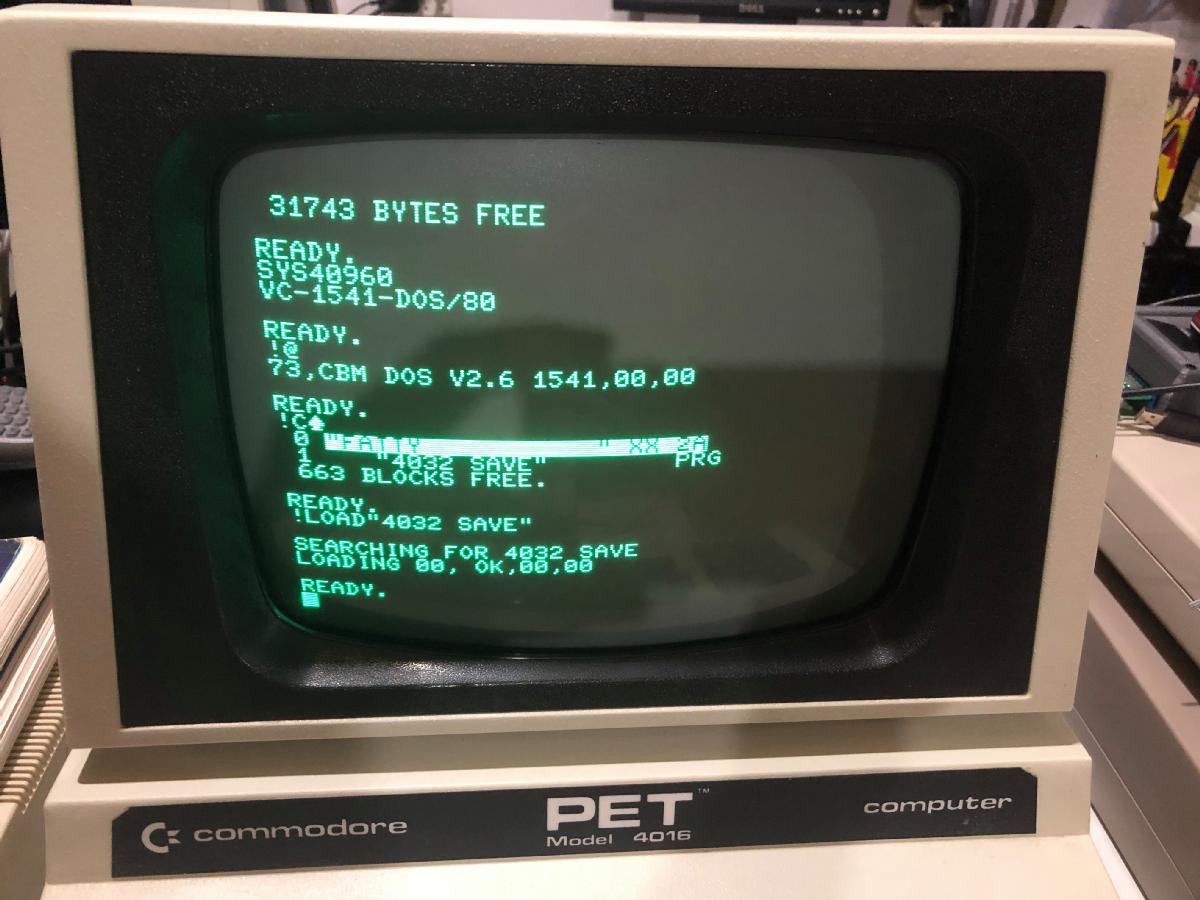
I had accidentally inverted both, the clock and the data input due to a wrong jumper setting. This did not work, of course. The 8032 crashed on the first 1541 access. I have quickly found the problem (the jumpers were labled incorrectly on the silk screen). After configuring the interface properly, I have seen this:
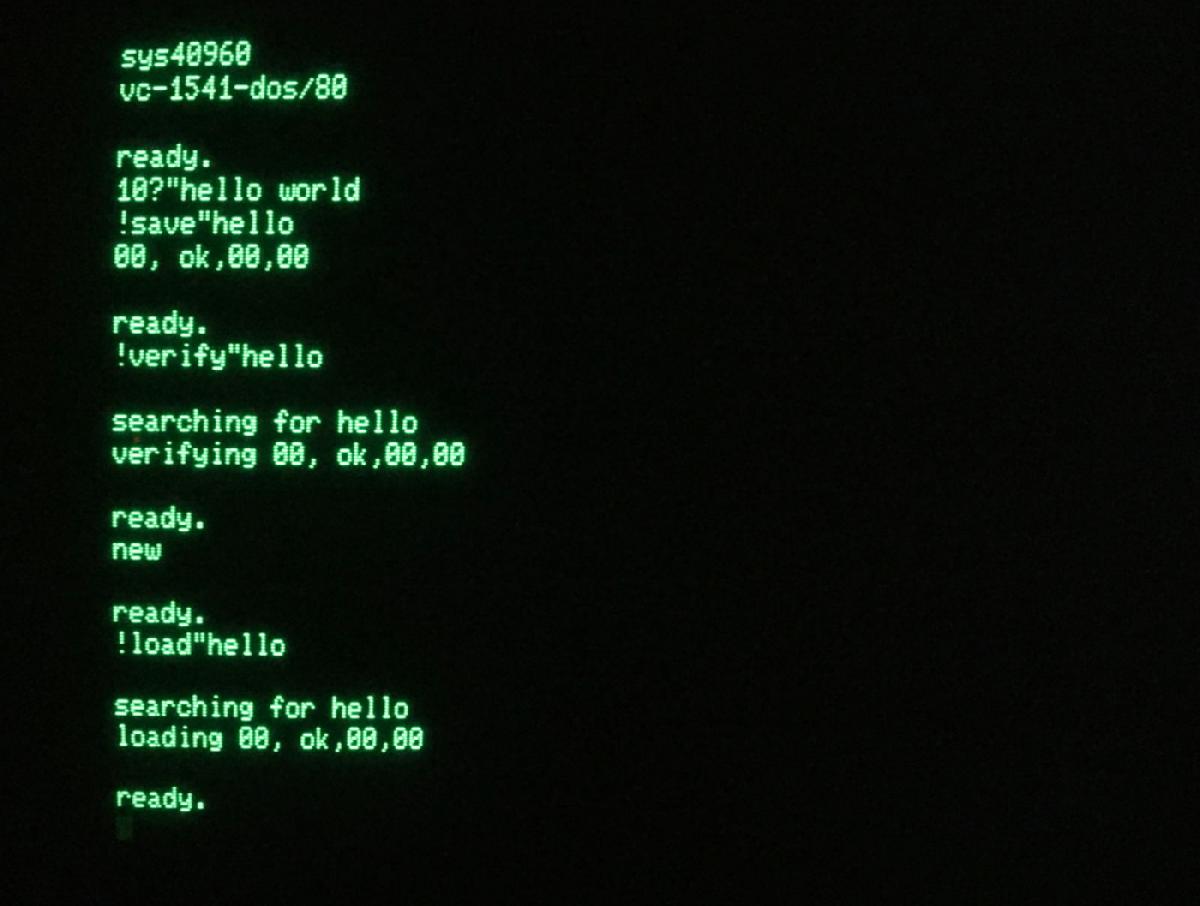
Trying !SAVE, !VERIFY and !LOAD
I have also tried out to write and read sequencial file. The syntax is a bit different.
The open instruction looks like this:
!open#1,"test,s,w"
There is no secondary address or the file number is the secondary address. I wrote a little program for writing an SEQ file named test.
2 print"scratch file"
5 !@"s:test"
7 print"open test for writing
10 !open#1,"test,s,w"
20 fori=1to100
30 !print#1,"This is a test"
40 next
50 !close#1
5 !@"s:test"
7 print"open test for writing
10 !open#1,"test,s,w"
20 fori=1to100
30 !print#1,"This is a test"
40 next
50 !close#1
I then wrote a program for the C64, that would display the content of such an SEQ file.
50 INPUT"FILE NAME";N$
70 OPEN2,8,2,N$+",S,R"
80 INPUT#2,A$
90 PRINTA$
100 IF ST<>0 THEN120
110 GOTO80
120 CLOSE2
70 OPEN2,8,2,N$+",S,R"
80 INPUT#2,A$
90 PRINTA$
100 IF ST<>0 THEN120
110 GOTO80
120 CLOSE2
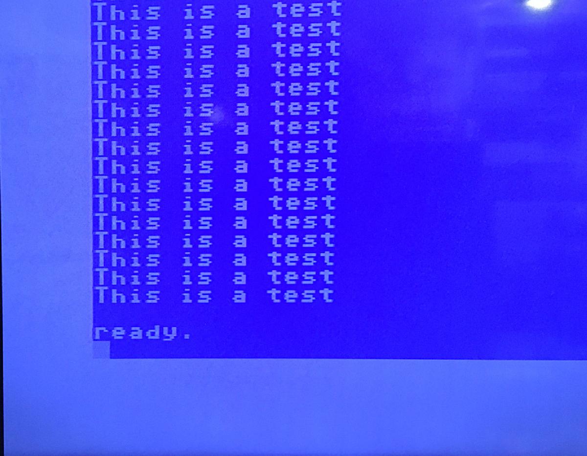
The content of the file TEST (SEQ)
The result looks ok.
As of now, I did not manage to read back the same file on the 8032. If I use
!open#1,"test,s,r"
I will get a "63,file exists,00,00" error message. after changing the file number to 2, I don't get this anymore ("00,ok,00,00"). But I get a status st of 66. That is bit#1 (time out) and bit#6 (EOI:End Of Information).
I then have tried all file numbers from 0 to 15. I get the described error for 1, I get a syntax error for 15 (which verifies, that the file numer is acually a secondary address - 15 is the command channel and the file name is not a proper instruction. This shows, that the number after the # is interpreted as a secondary address.
I have tried reading with a speed dos 1541-II and a cbm dos 1541. Both the same. Hmmmmm...
Anyways, I wanted to test all floppy disk drives and emulations, that I have.
These are:
● 1541
● 1541-II
● 1581 (a repair guest)
● SD2IEC
● Pi1541
● Oceanic OC-118N (a 3rd party 1541-II copy)
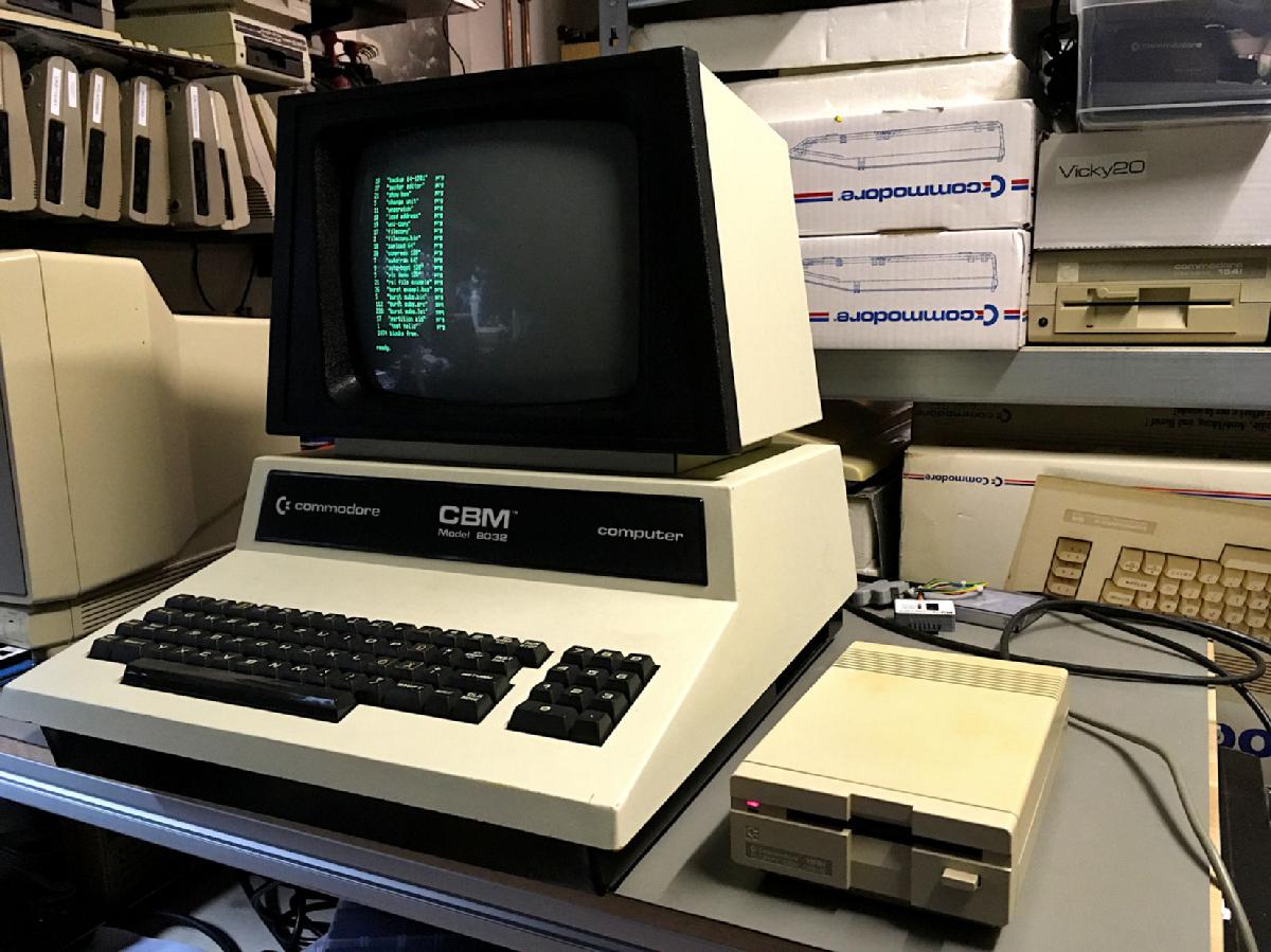
All drives worked. The only exception was is the !catalog command with the SD2IEC. A !load"$" does work, though.
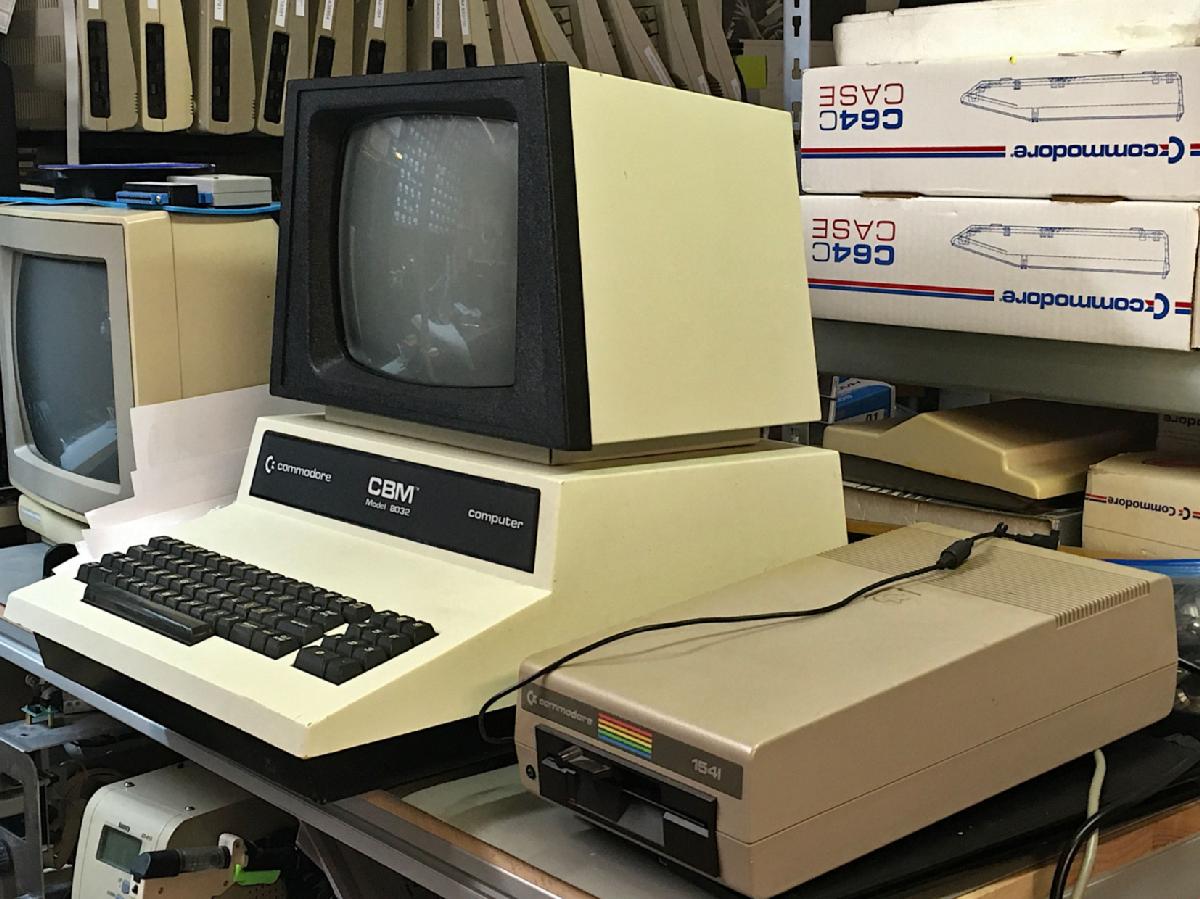
Test Setup with the 1541
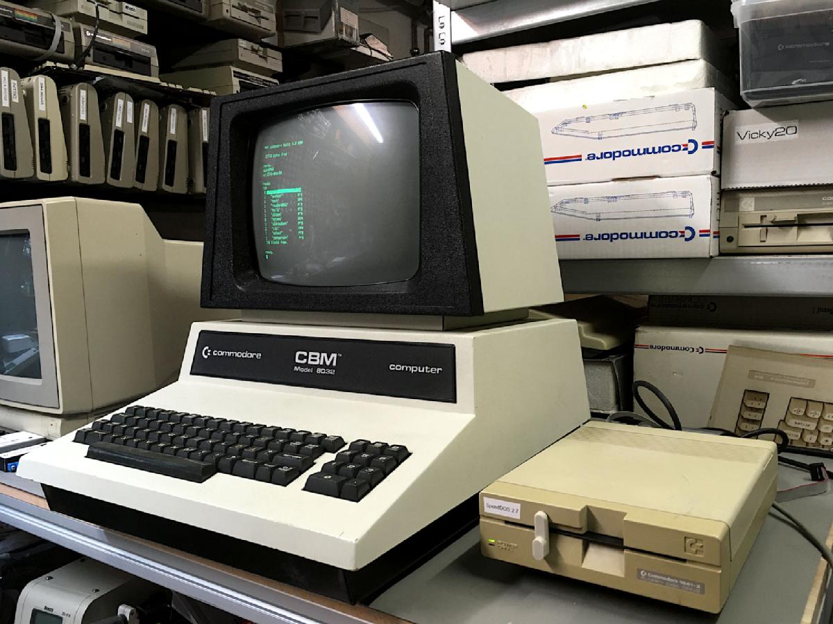
Test Setup with the 1541-II
Test setup with the 1581
Test Setup with the OC-118N
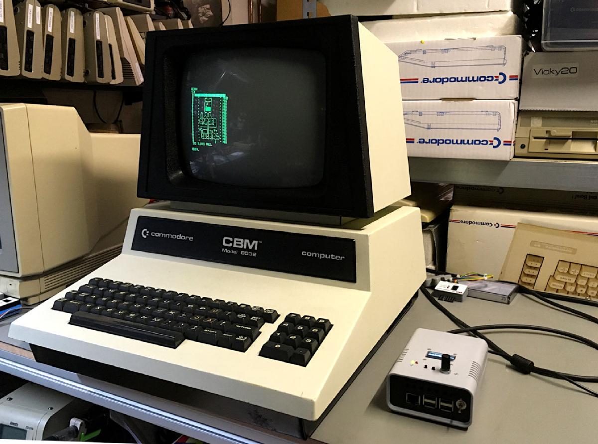
Test Stup with the Pi1541
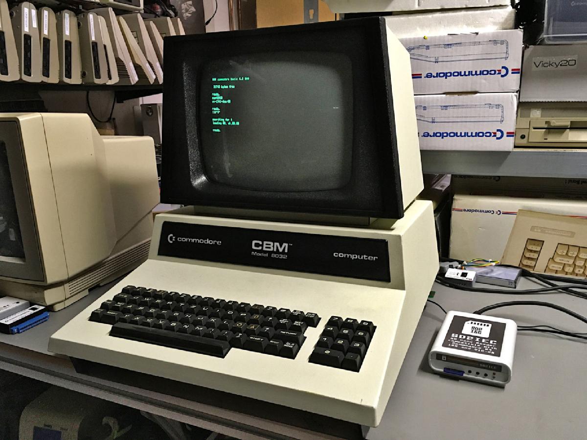
Test Setup with the SD2IEC
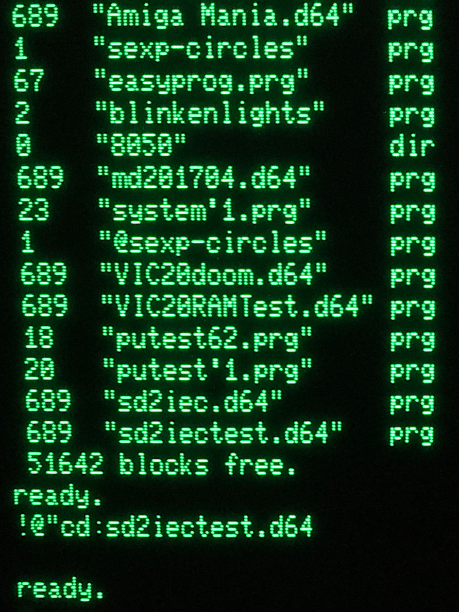
Change Directory command with the SD2IEC
I had sent Thomas Cjhristoph PCBs and he has built his own PET/CBM 1541 adapter. The tests with his FAT 40 4032 look promissing.
Test with the FAT40 / Photo by Thomas Christoph
Test with the FAT40 / Photo by Thomas Christoph
Note
Mike Naberezny did some further investigation of the EPROM binary/disassembly and has found out some interesting details. Check out his github repository.
This is:
"
● BASIC 4.0. The code makes many calls that are specific to the BASIC 4.0 ROMs.
● Due to its use of location $87D0, the code requires an 80-column machine to fully function. $87D0 is in the 80-column screen RAM but is not part of the visible screen. This location is required for the wedge commands !print#, !get#, !input#, and !cmd#. These will not work correctly on a 40-column machine. However, the other commands will work.
"
He has also included a more complete instruction list, than mine.
[...to be continued...]
Released on Github
The hardware was released as open hardware on github: https://github.com/svenpetersen1965/PET_CBM_1541_Adapter