


Cable Making
Cable making is the part of a project, that is hard to avoid. Especially, when the projects consist of more than one PCB or has external modules, like an OLED display. It is not necessarily the most joyful part of a project.
Content
1. Soldering
1.1 DIN Connectors
2. DuPont Cables
3. Ribbon cables with IDC type connectors
4. Crimping
4.1 Closed Barrel Crimps
4.2 Open Barrel Crimps
4.2.1 Two Pass Crimp Tools
4.2.2 Crimping a Molex KK (2.54mm) Step by Step
4.2.3 Crimping a DuPont Terminal Step by Step
4.2.4 Crimping the Molex KK 3.96mm (SPOX)
4.2.5 Crimping the Molex KK 5.08mm (SPOX)
4.2.6 One Pass Crimp Tools (my prefered tools)
Soldering
The classic "solder a cable to a connector" method is hard, since normal humans are lacking of at least one additional hand. The so called "helping hand" might be of some use here, but it is still a time consuming task.
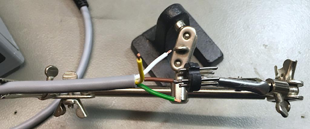
Soldering a DIN-conector with the "helping hand"
One problem when soldering cables is the high risk of dry solder joints. The terminals have a small mass and the solder joint does not cool down very quickly. There is plenty time to move before this happens.
Another problem is that while soldering, the terminal gets so hot, that the plastic insulator starts meltingh and the whole connector is deformed. Have you ever soldered a ribbon cable? the insulations melts, shrinks and does everything you do not want it to do.
So, soldering should not be the preferred method of cable making.
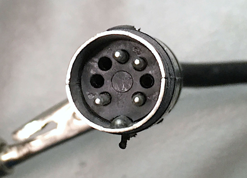
DIN-Connectors
The only type of connectors, that I have soldered while the past years were DIN connectors. They were popular for audio-equipment and also for "vintage computers" like the Commodore VIC-20 or C64. DIN means "Deutsches Institut für Normung", the German institute for standards. There are different DIN standards for connectors, but the one, that applies for this kind of circular connectors is DIN 41524.
Circular connectors are still in use for industrial applications and can be quite good and reliable, the consumer equipment DIN connectors are actually not really great. They are fragile, a bit fiddly to assemble and hard to solder.
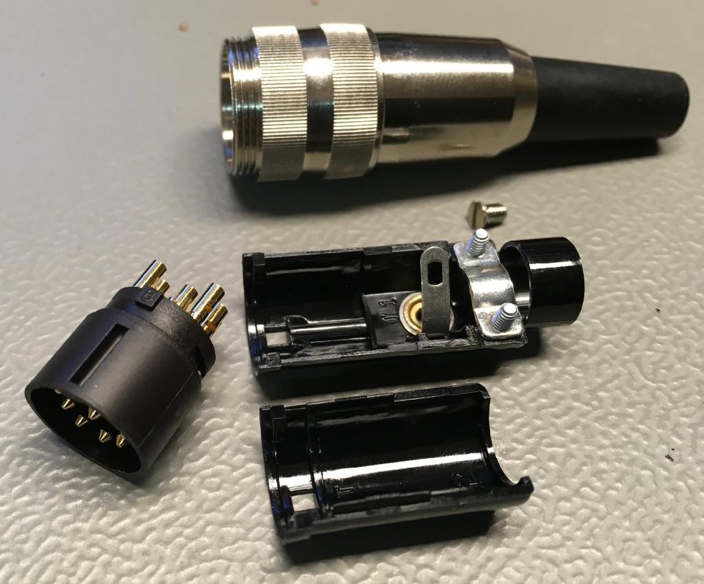
Usually, the DIN connectors consist of four parts:
● the connector body
● the two metal shells
● the plastic outer sleeve, that holds the parts in place
The solder side of the cylindric terminals are solder cups, a drill, that is more or less suitable for inserting the wire strands. I have found two types of solder cups, complete closed ones and half open ones.
It is easier to insert the wire strands into half open solder cups.
There are more expensive DIN connectors of a better quality, like the Lumberg SV-80, that is used in the A/V-Adaptor project.
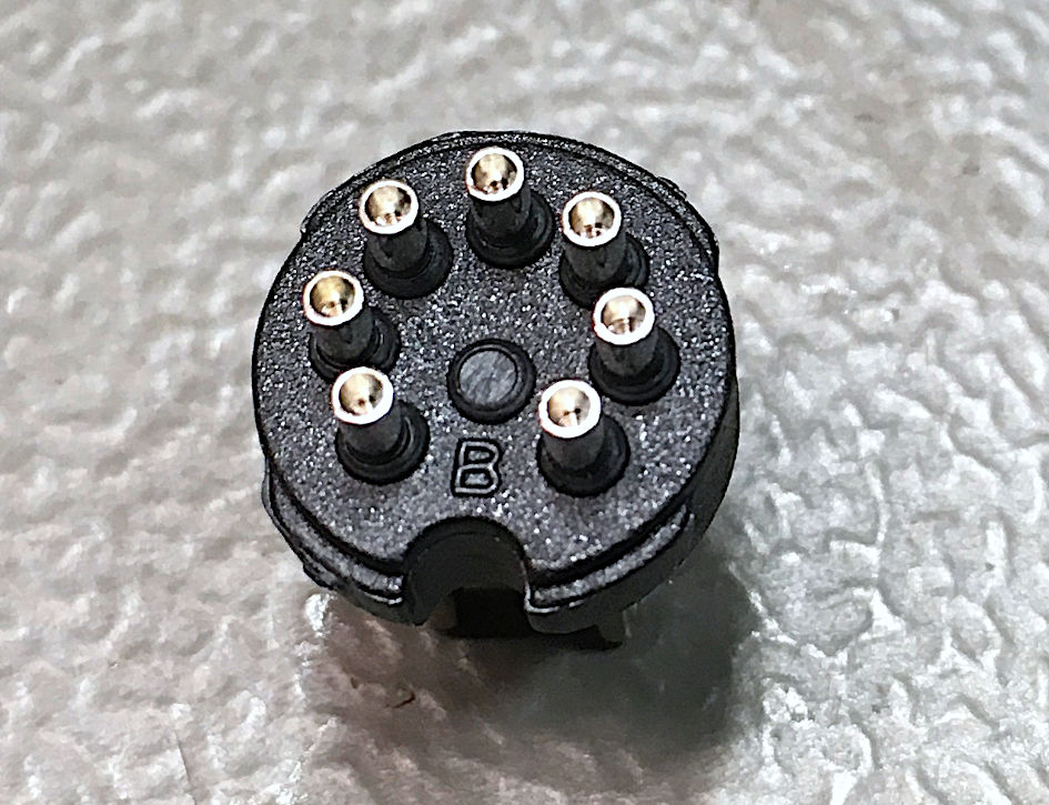
Lumberg SV-80
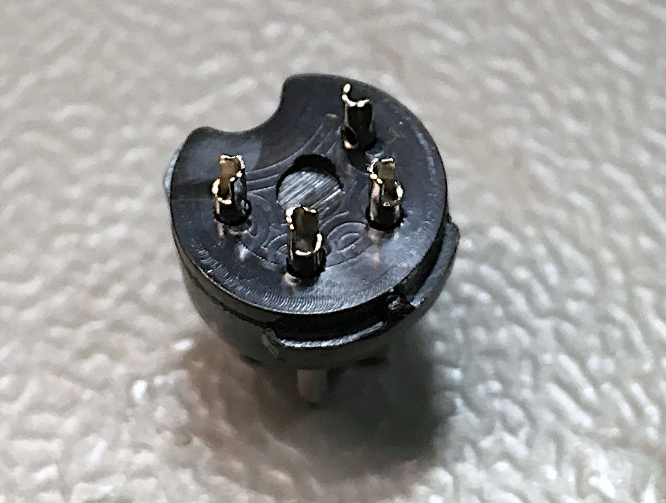
The C64 power connector is a crimp type connector. The terminals are crimped to the wires and inserted into the body afterwards. Not all circuits are populated with terminals:
C64 power conector
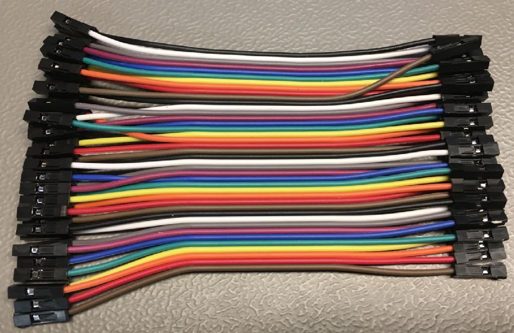
Ribbon cable with DuPont connectors
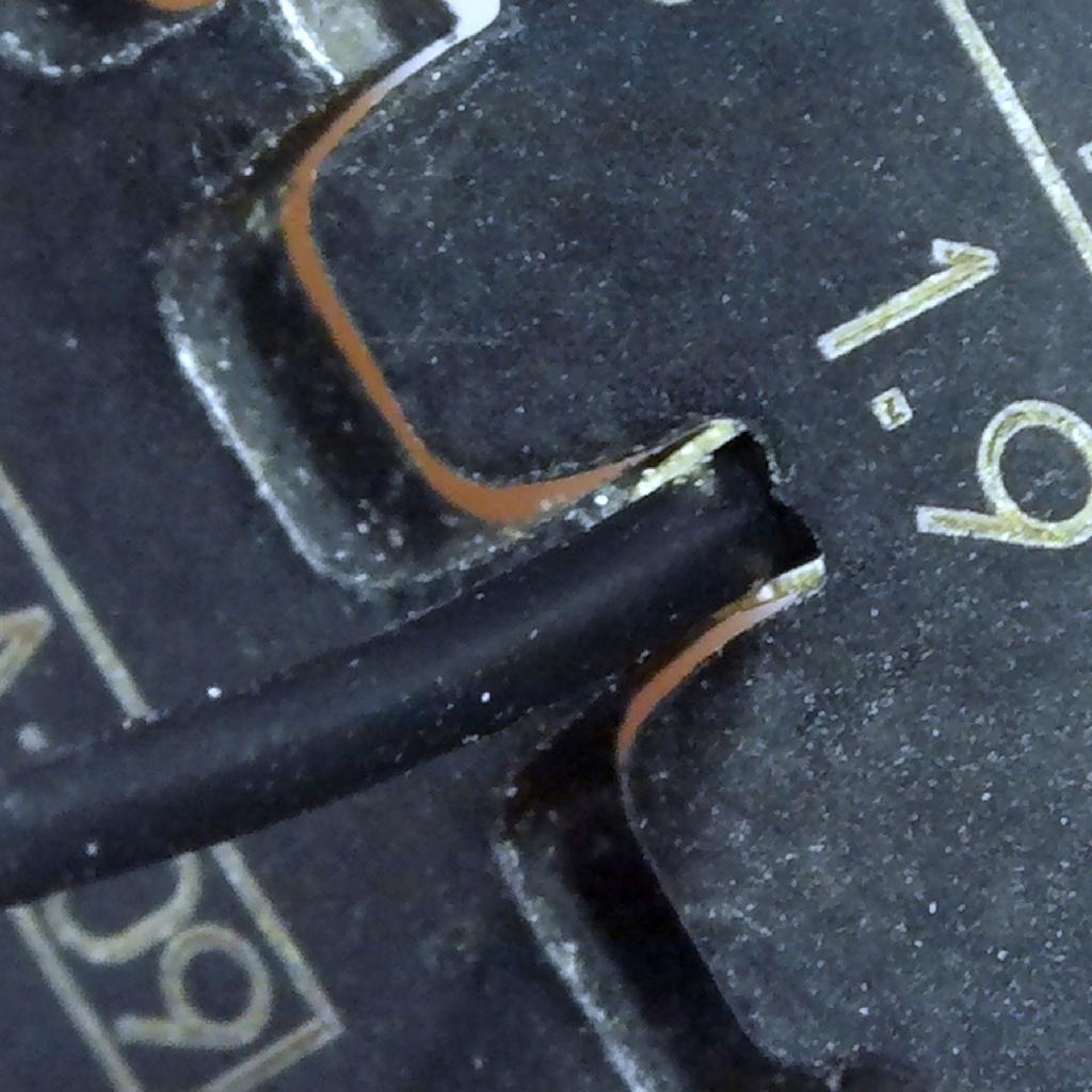
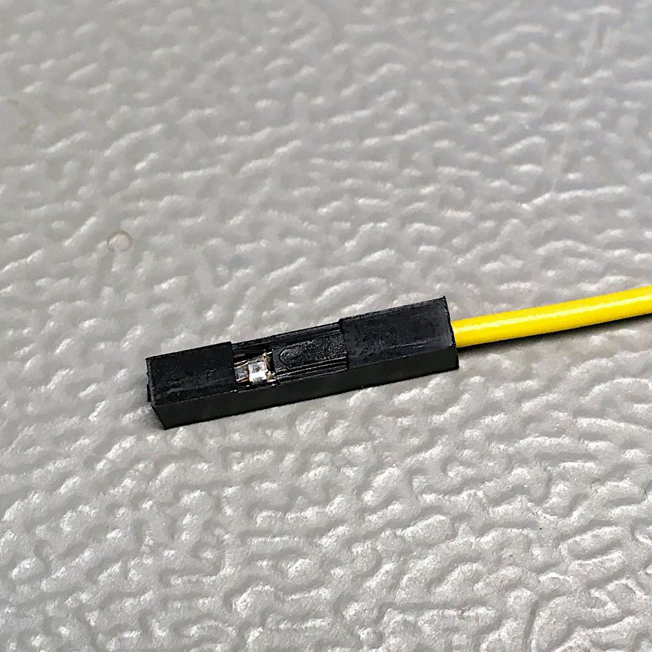
Those cables can be bought cheap from ebay, Banggood or AliExpress for little money typically in lengths of 10cm, 20cm and 30cm. There are male and female DuPont (aka Mini-PV) terminals, which work with the same crimp housings. The required number of wires can just be teared off and the connectors can be used as is (one way connectors) or the crimp housing can be replaced with a differnt number of terminals per housing. It is easy to remove the housing by lifting a little plastic tongue and pulling out the cable with terminal. Inserting the ready crimped cables with terminals into another housing is even easier. You just need to make sure, the terminal is in the proper orientation so they can snap in properly.
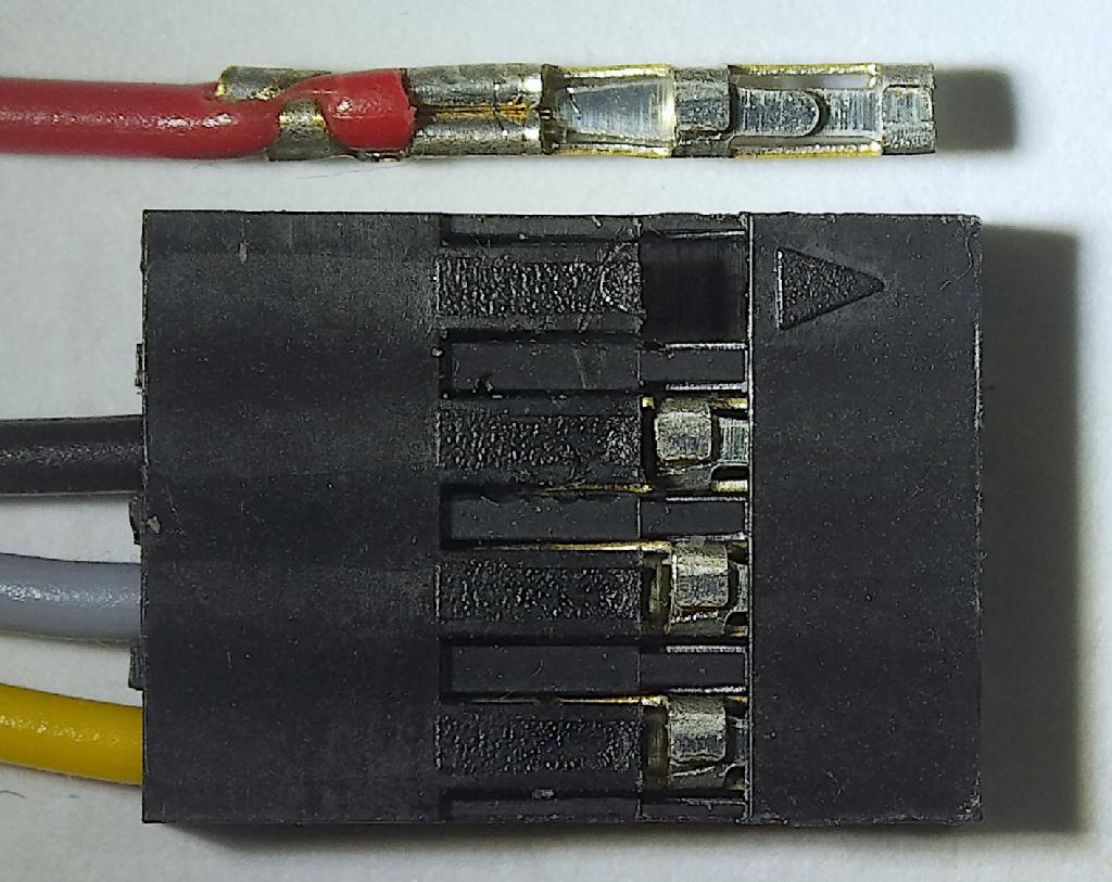
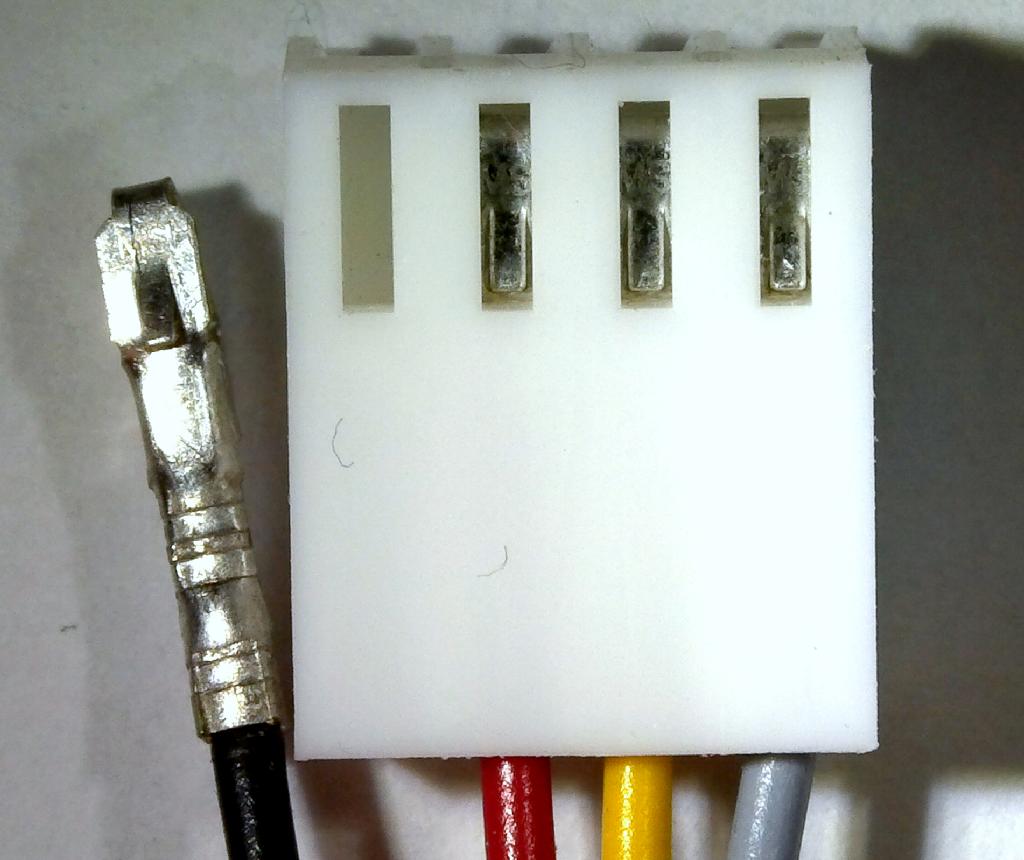
DuPont four way crimp housing and cable with crimp terminal
The previous image shows a four way crimp housing, one terminal is extracted. It illustrated the orientation of the terminals in the crimp housing for a proper installation of the crimp terminals in the housing.
For DuPont crimp housings, the assortment boxes from ebay, AliExpress or Banggod are a good way to have something around to tinker with.
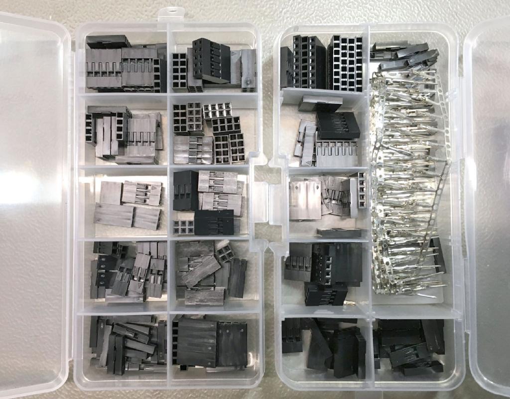
DuPont connector assortment box
Ribbon cables with IDC type connectors
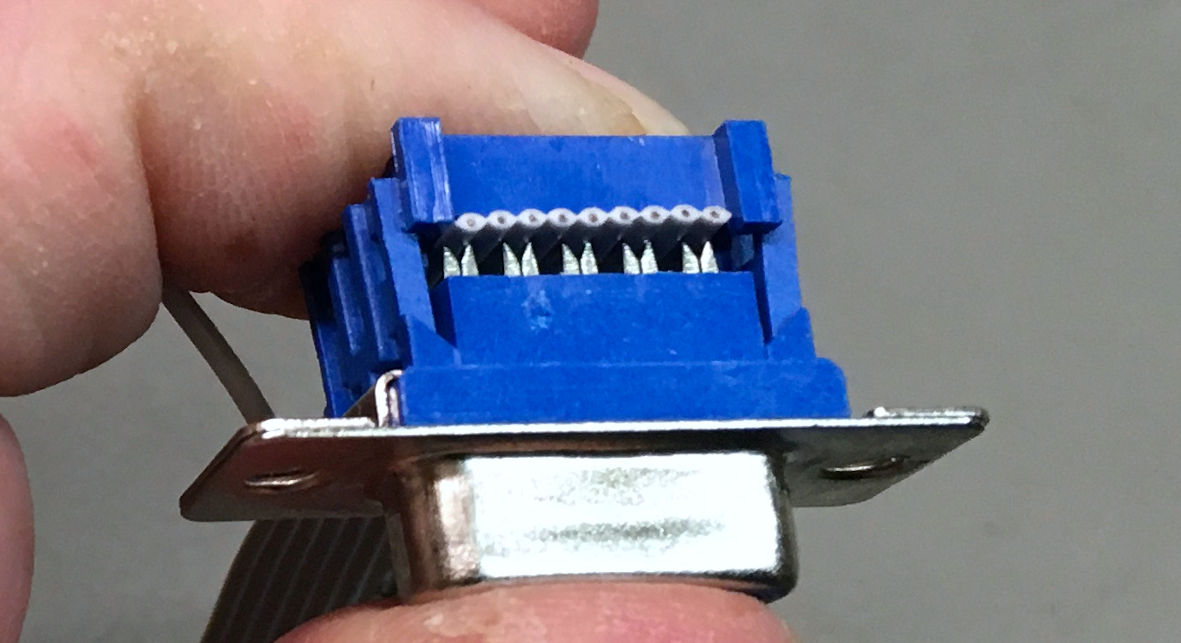
IDC means insulation-Displacement Connector. It is a pretty easy way to get multiple way connections with one pass. Just insert the ribbon cable into the connector and compress the connector. Little blades are cutting through the insulation of every wire of the inserted ribbon cable and make a reliable connection. It is really not much harder than this. I pay attention, that I cut the ribbon cable straight (90° plus minus a few) and alight the end of the ribbon cable with the oposite side of the connector. Then I carefully compress the connector with a small vice. There are also tools for this, but I find the described way easiest.
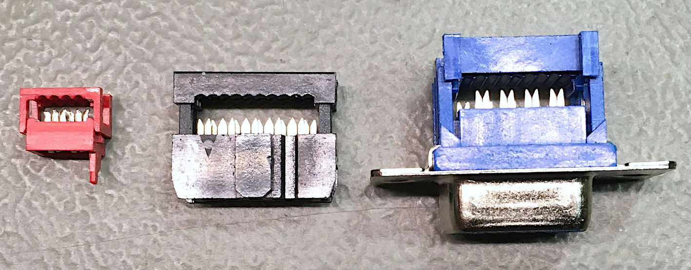
Different IDC connector types (MicroMatch, IDC receptacle/2.54mm pitch), D-Sub)
The previous image shows the IDC connector types, which I use in my projects (there are some more). all of them fit on 1.27mm/0.05" pitch (standard) ribbon cables.
The (red) MicroMatch (left) connector has some advantages: It is very low profile and it is available with many (even) numbers of circuits, like 4, 6, 8, 10, ... The disadvantage is, that the coding pin breaks off easily and then, it can be connected in the wrong orientation.
The (black) IDC receptacles are very wide spread and sit well in (male) box connectors. It is not available for all numbers of circuits. Common are (6), 10, 14, 16, 20, 26, 34, 40 and 50 circuits. It is easy to install, cannot be connected the wrong way, is robust and and available from many manufacturers. There are also 2.0mm pitch IDC receptacles (which require a 1.0mm pitch ribbon cable). A strain relief can/should be installed.
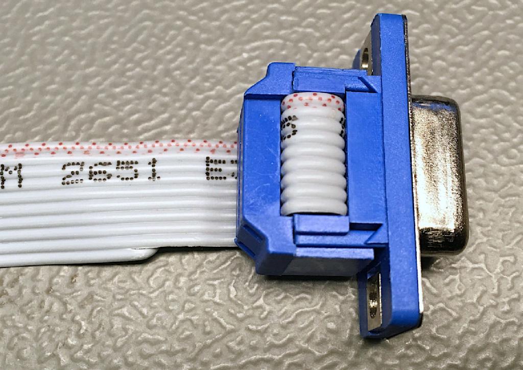
The (blue) D-Sub connectors (right), have been pretty popular in the last millenium. Serial interfaces, parallel interfaces, MIDI/Game ports were a typical allpication on the PCs. It is a very reliable connector and is still in use for several industrial applications. It also comes with a strain relief. Typical numbers of circuit are 9, 15, 25. The Commodore Amiga makes use of 23 ciruits, which is not really available nowadays.
There are special tools for compressing the IDC connectors. They are comfortable and provide guides for the ribbon cable, so that they are connected perpendicular to the cable. You need a template for very kind of connector, they are for industrial purposes, when a high number of cables have to be made. . I had access to this kind of press, but I always used my (small) vice. It is my favorit tool for this purpose.
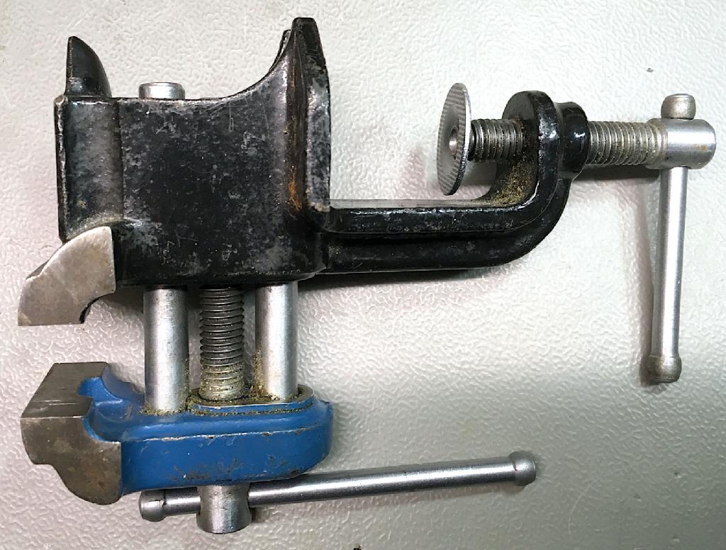
The vice - my favorite tool for IDC connectors
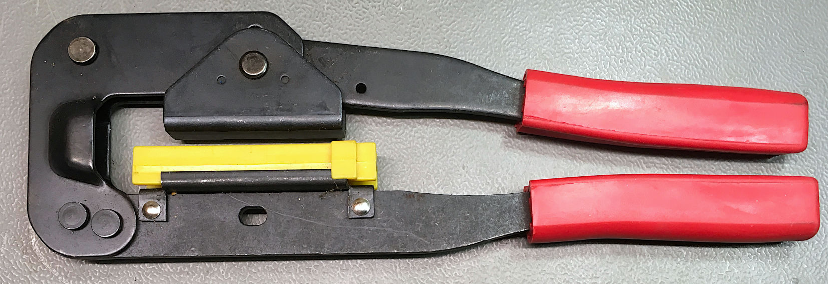
An IDC receptacle pressing tool
The IDC tool, shown in the previous image, was not expensive, but it is much less versatile than the vice. It can only be used for 2.54mm pitch IDC receptacles.
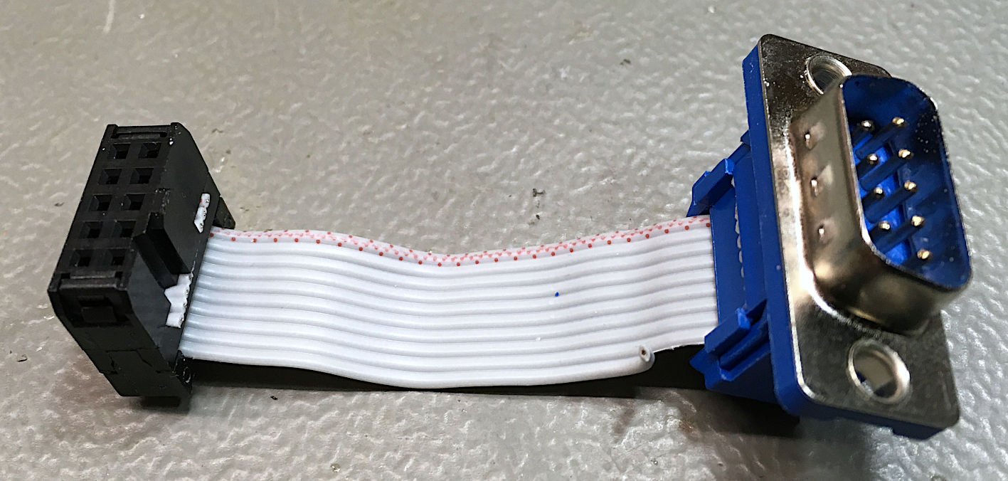
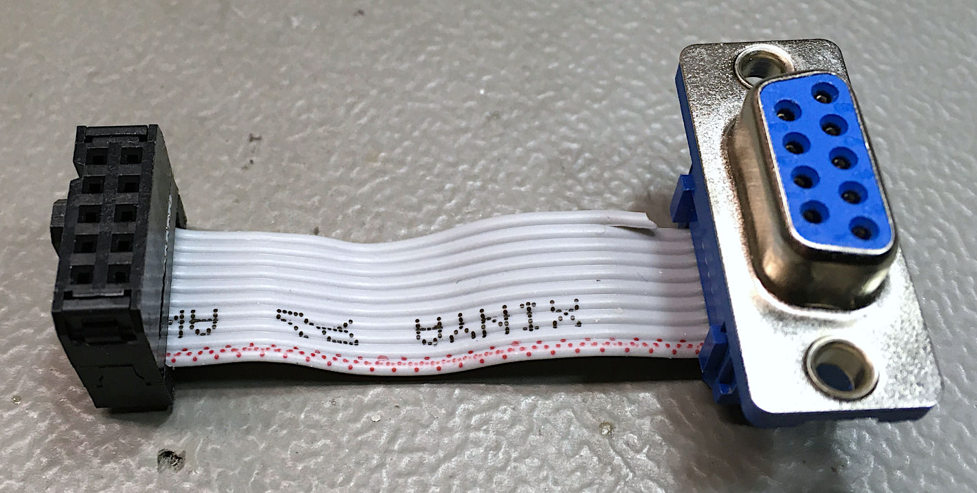
Male and female D-Sub cables
Previously, two cables with a female and a male D-Sub connector are shown. Please notice, that pin 1 is on oposite sides of the top row of female (right) and male (left) D-Sub connectors. The IDC receptacles are in different orientation and the (red) maked wire number one of the ribbon cable is on different sides. Since the IDC receptacles have 10 circuits and the D-Sub has 9 circuits, one wire has to be clipped of. This is the 10th wire, not the marked pin one wire.
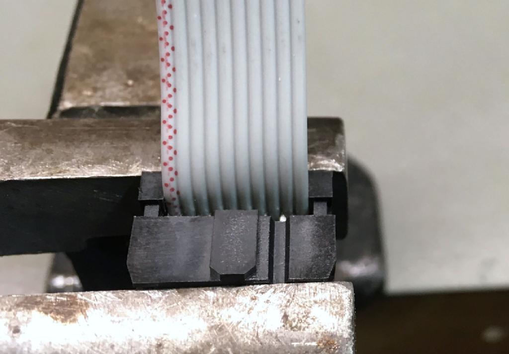
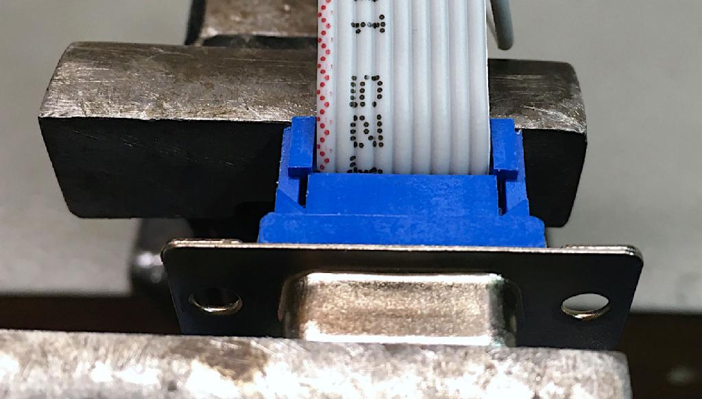
The six steps shown previously:
Step 1: Insert and align the ribbon cable, put is in the vice and compress the connector
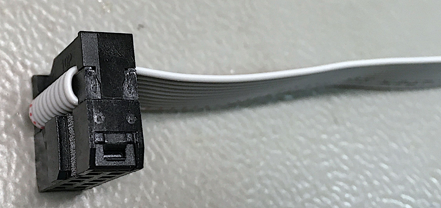
Step 2: 180° turn and installation of the strain relief
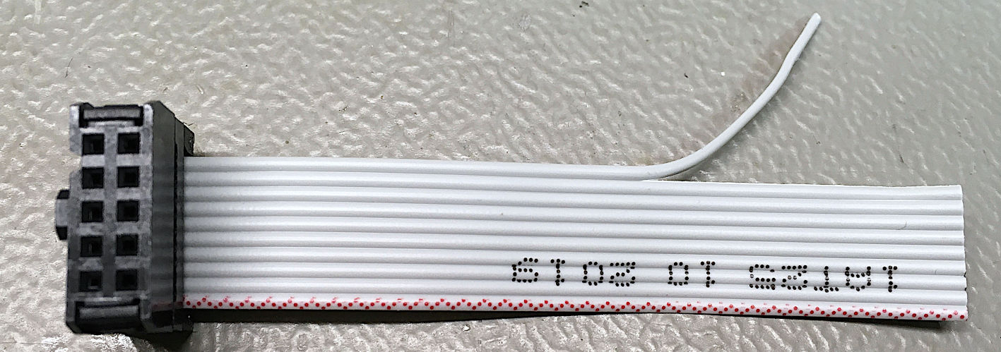
Step 3: separate the 10th wire
Step 4: insert and align the ribbon cable in the D-Sub connector
Step 5: Compress the D-Sub connector in the vice
Step 6: 180° turn and istallation of the strain relief
Notes:
● The ribbon cables can be inserted on both sides of the connectors. Before you compress the connector, you need to make sure, you have done it the right way.
● The strain relief causes a 180° turn of the cable, so insert it from the oposite side, that you finally want it to exit the connector
● The alignment of the ribbon cable does not need to be 100% accurate, but it should not be completely off. Do it as well as possible for you.
● Compress the connectors carefully. When listening carefully a slight "click" might be audible, when the parts get into their end position.
● The wire for pin one should be the marked wire
Crimping
Mid of the 20th century, AMP invented the electrical crimp. It does not require soldering, it can be achieved with a suitable crimp tool, it is much faster than soldering and the quality of the connection is better than a solder joint:
● A good crimp is gas tight. Water and oxygen cannot corrode the joint
● Since no alloys (such as solder) are involved, the joint is mechanically stronger
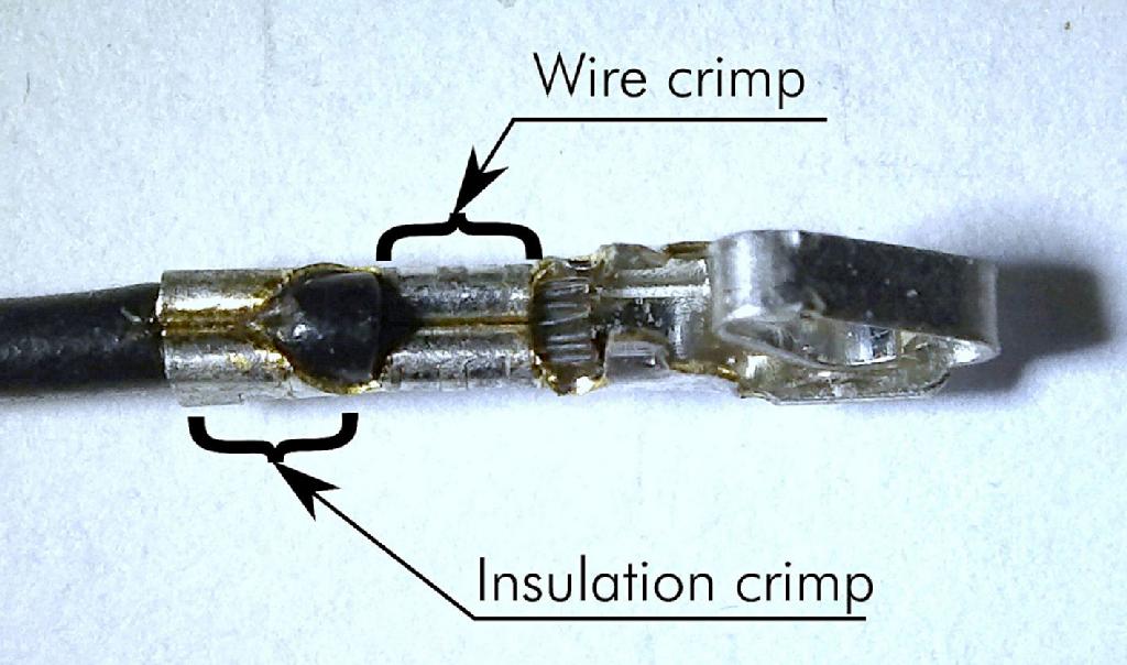
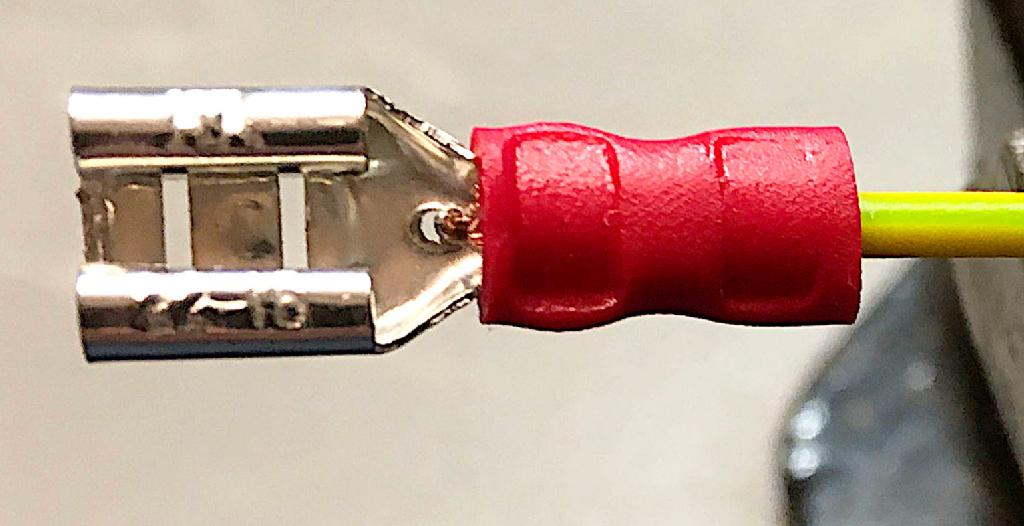
A crimped connector terminal (open barrel)
The drawback of crimping is the requirement of special tools. Those can be crimping machines, which can carry out 1000s of crimps per hour or manual crimp tools, which are capable of maybe 100 terminals per hour (in case you are a very concentrated worker and everything is set.
The crimping machines strip off the insulation with a specifies length and carry out both, the wire and the insulation crimp in one pass, they have to be adjusted carefully before.
Manual crimp tools do not require adjustment, but they do not strip off the insulation and require one or two passes for the wire and the insulation crimp. They can be quite expensive (up to $1000), but this is not always the case. Semi-professional crimp tools are available between $10 and $50. In case you have to deal with cable making more than just once, it might be a good idea to get into crimping.
Closed Barrel Crimps
A couple of connectors such as ring, fork and spade connectors provide a closed barrel crimp, a closed cylindrical opening in which the wire strands are inserted and which is then deformed to form the crimp and hold the wires. These types of terminals are fully or partial isolated. The color of the insulation indicates the suitable cable diameters.
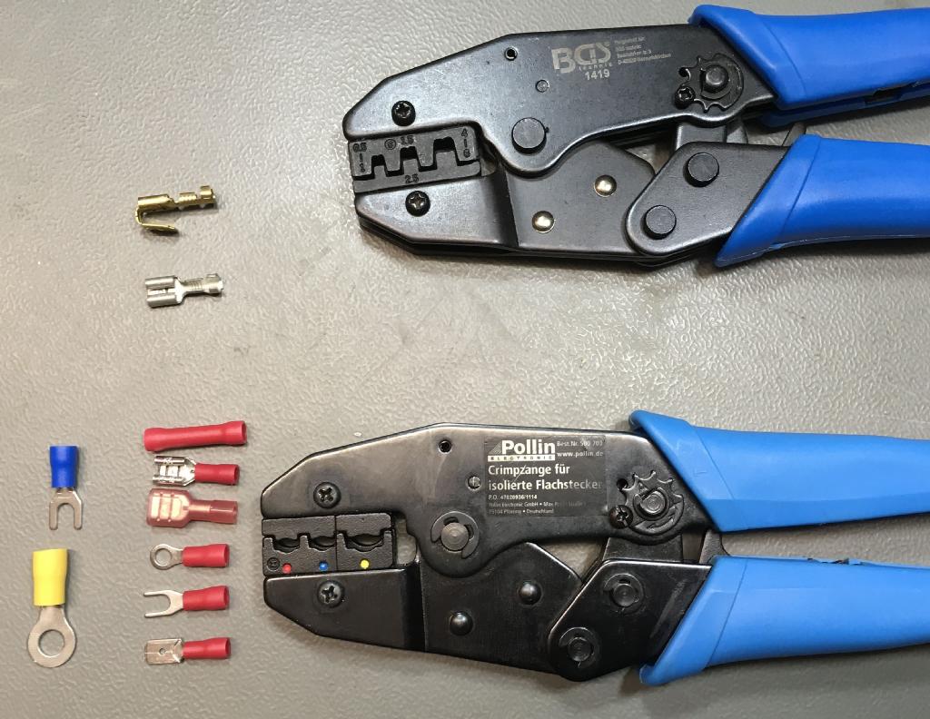
Barrel crimp tools
The previous image shows crimp tools for the connector types mentioned before. The lower tool is suitable for isolated connectors (closed barrel crimp). On the left side, some of the connectors are shown, that can be crimped with each tool.
Fully insulated connectors are recommended, for mains switches and other high voltage connections, fully isolated connectors are recommended. The dots on the tool show the connector color, that can be crimped with the respective slot/die.
The first step is stripping off about 5mm of the insulation. This can be done with any kind of wire striper. The wire strands should not be cut off while doing this.
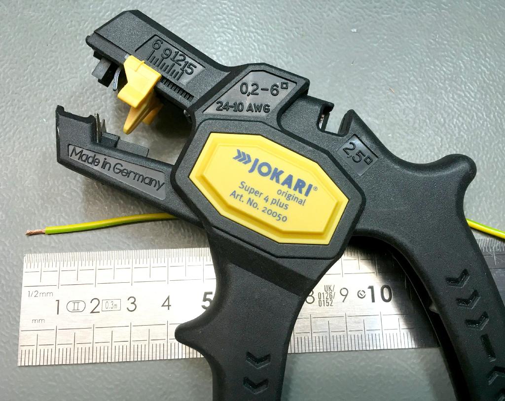
Wire stripper
For the FastOn connectors, it is receommended to strip off the insulation about 5mm.
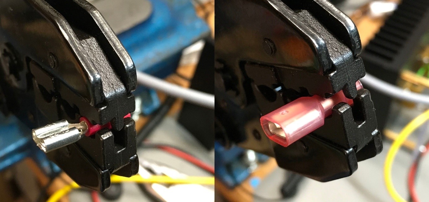
FastOn connector in crimptool
The next step is the insertion of the connector into the crimp tool. Most models of the crimp tools have a ratcheting mechanism and hold the connector. The connector should not be compressed before inserting the cable.
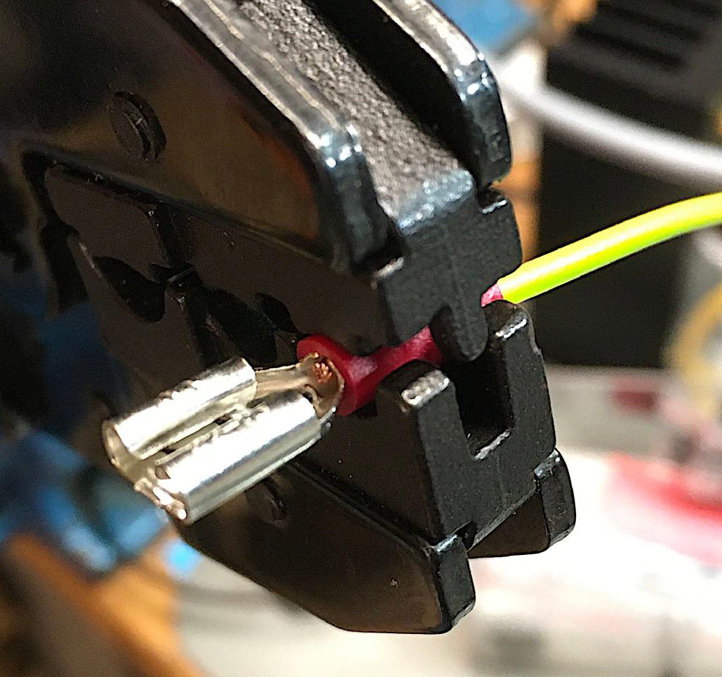
Inserting the cable and crimping
The cable is inserted all the way until the insulation touches the (metal) crimp barrel inside. The wire strands should all be inserted and be visible on the other side of the crimping barrel, but should not stand out too far. This would mean, that too much of the insulation was stripped off.
Finally, the tool is compressed all the way until the ratcheting mechanism open again. The crimping barrel should be nicely compressed and when pulling the cable, it should stay attached to the connector. The pull test is for verifying, that the crimp was conducted well.
Crimped FastOn connector
The crimp tool for this kind of connector can be pretty expensive (>$200), but it is not really necessary. The shown tool was about $10 and works pretty well. A tool with a ratcheting mechanism is strongly recommended.
Open Barrel Crimps
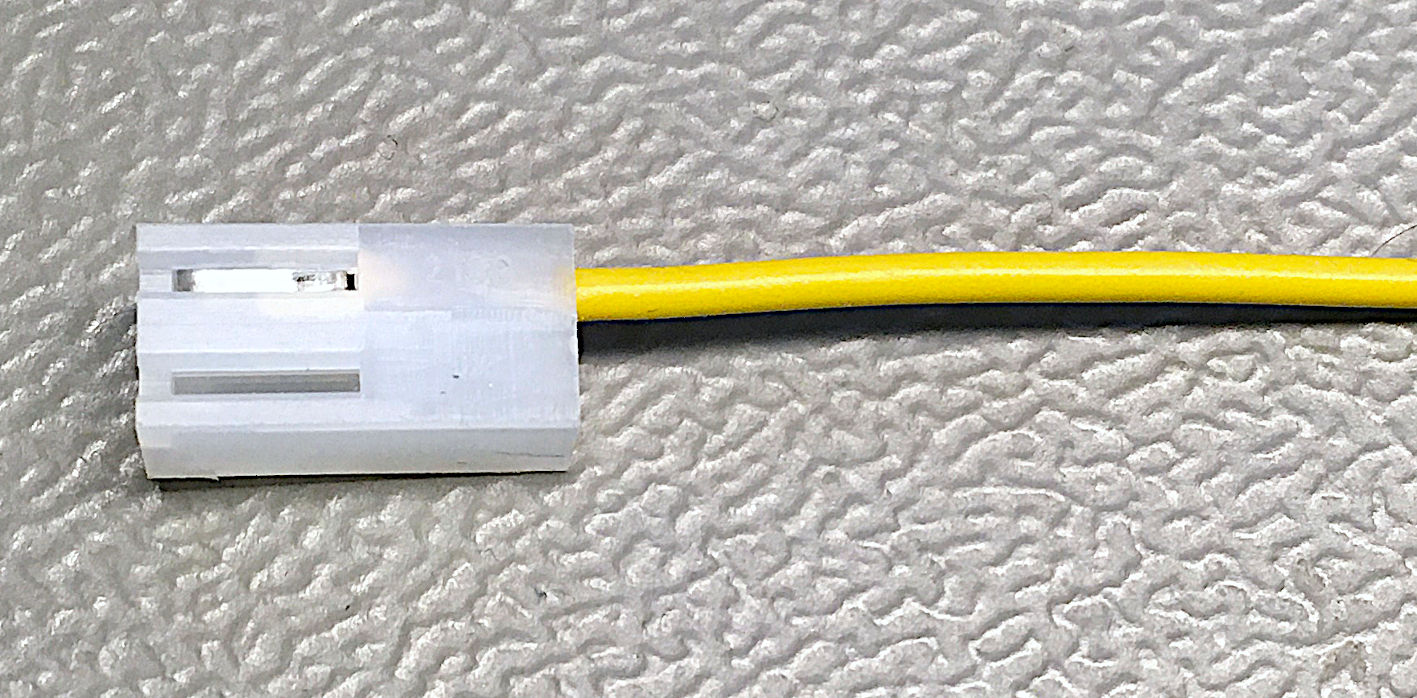
Open barrel crimp connectors have U-shaped metal ears, that are folded and compressed over the stripped off end and a part of the insulation of the cable. A typical application is multi-circuit connectors, such as the wide spread DuPont (aka Mini-PV) connectors, Molex KK connectors etc.
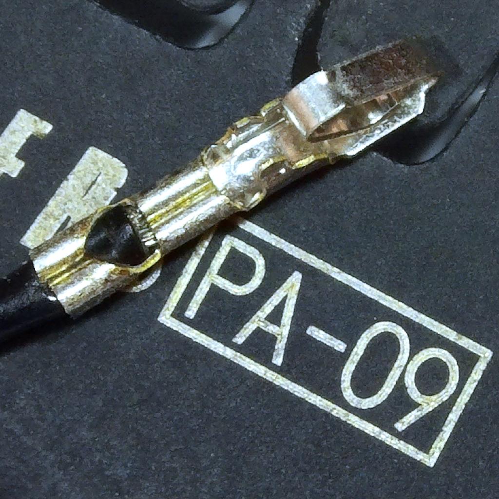
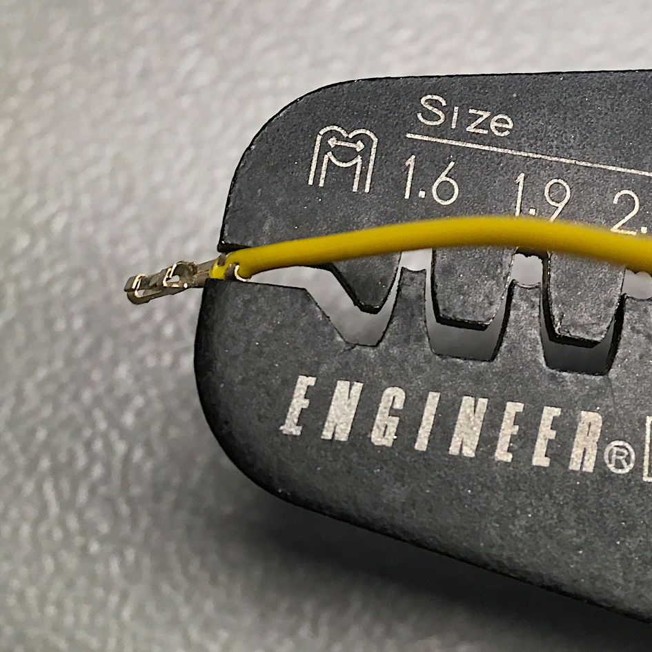
DuPont connector (four way) crimped with the Engineer PA-09
Molex KK (2.54mm pitch)
A multi-circuit connector typically consists of a crimp housing and crimp terminals, which are first crimped to wires and then inserted into the crimp housing, where they are held by some kind of snap-in mechanism.
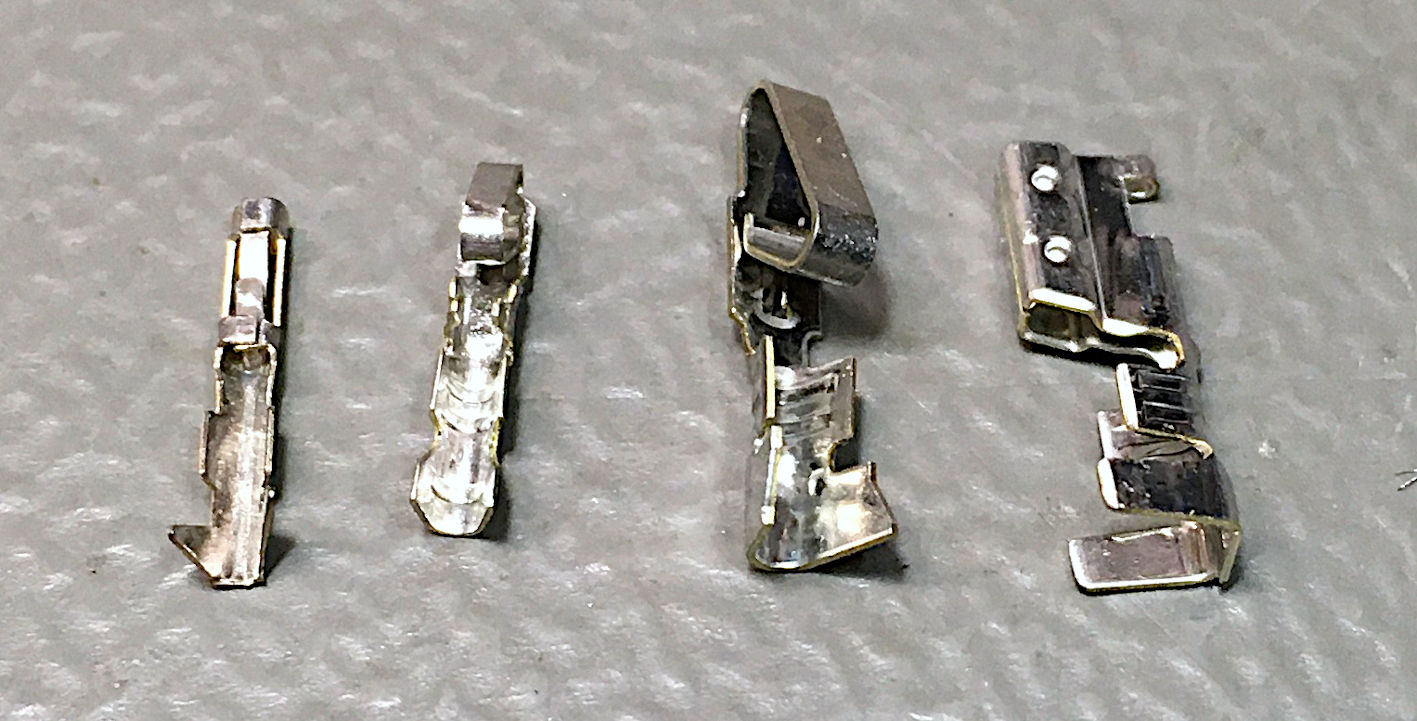
Crimp terminals (left to right: DuPont, Molex KK 2.54mm,
Molex SPOX 3.96mm, Molex SPOX 5.08mm)
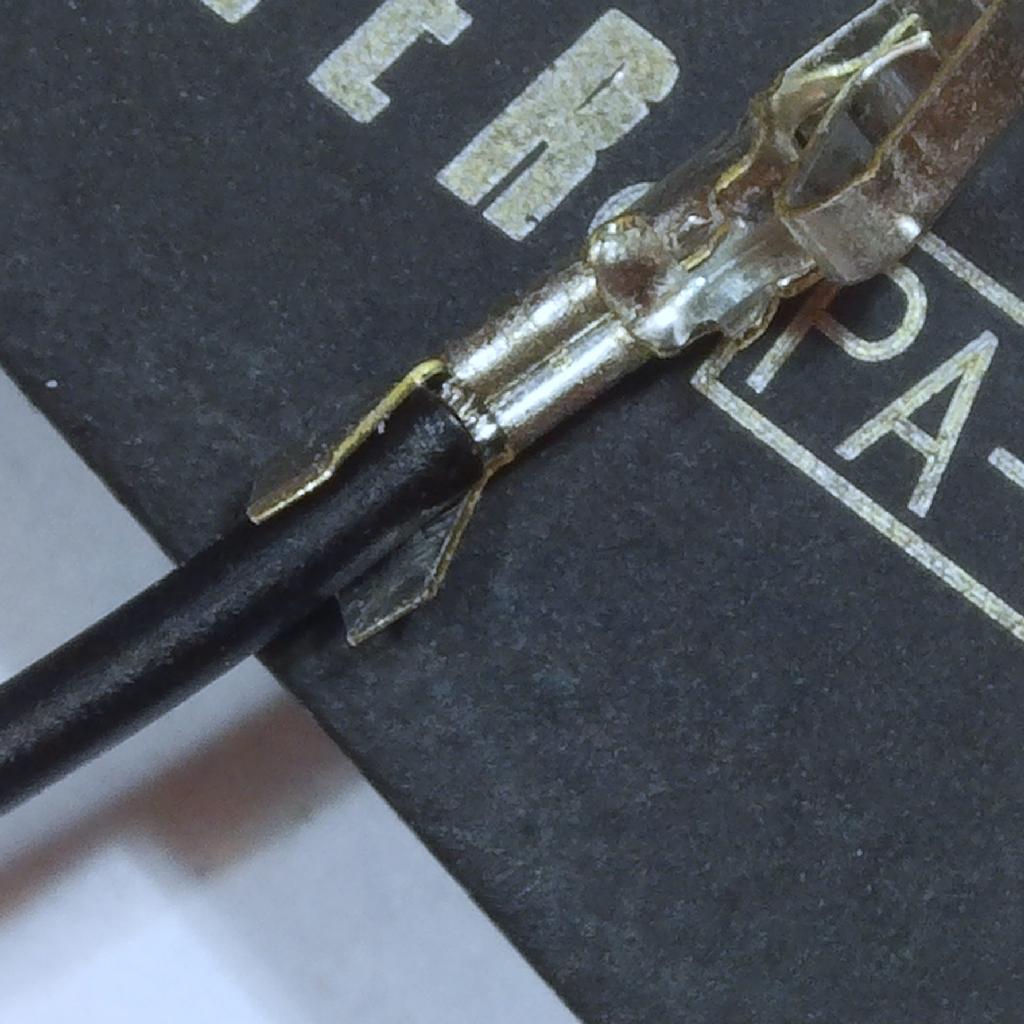
All open barrel crimps consist of two different crimps: The wire crimp and the insulation crimp. The wire crimp must not include any part of the insulation, the insulation crimp should hold the insulation only.
Wire crimp and insulation crimp on a Molex KK terminal
A professional tool does both crimps in in one pass. Most of the more affordable tools have to crimp each part separately in different dies.
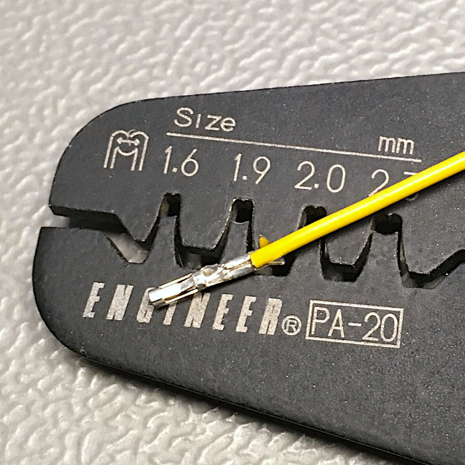
The width of the wire crimp ears is the length of insulation that has to be stripped off prior to crimping. For many contacts this is between 2mm and 2.5mm.
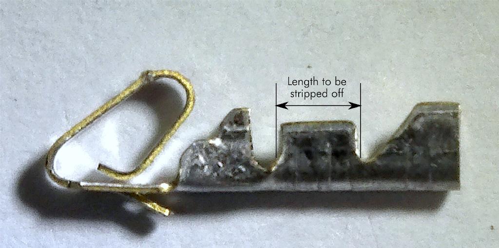
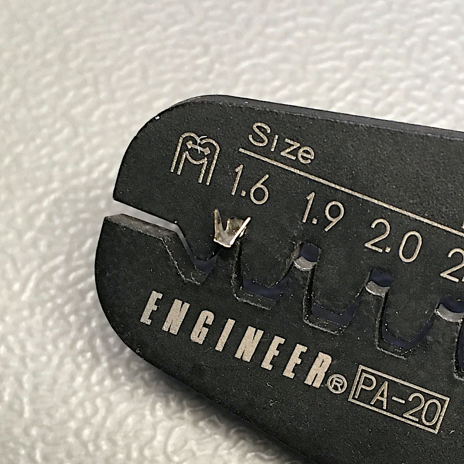
The ears, that determine the length of insulation that has to be stripped off
(Molex KK crimp terminal)
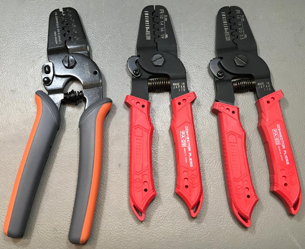
Crimp tools: IWISS IWS-2820M, Engineer PA-09 and PA-20 (left to right)
The previous image shows some common crimp tools. They have dies of different widths in which the crimp terminal and the wire are inserted. When the tool is compressed, the crimp is formed.
The wire crimp requires more (but not excessive) force than the insulation crimp. Excessive force can damage the wire and/or the crimp terminal, the diameter of the crimp connection will be too little so the nominal maximum current will not be reached. Too light force will not deform the wire strands enough, so that the crimp connection is not gas tight or the wire can even be pulled out if the terminal (pull test!).
My rule of thumb is:
For the wire crimp, press like you shake hands with a man, for the insulation crimp, press like you shake hands with a lady.
The crimping results of the IWISS IWS-2820M are half decent, the crimping results of the PA-09 and PA-20 are usually good. While the IWS-2820 is less than $20, the two Engineer crimp tools are about $50 each.
For DuPont terminals, there is a one pass tool, the SN-28B. I have heard bad things about it, but did not try it myself. I have ordered one two months ago, which did not arrive yet (as of March 27th, 2020). I will try it and report my own experience. I think, the two pass tools are more versatile, because you can combine different dies for a type of crimp terminals.
The Engineer PA-20 works for all crimp terminals, that I have used in my projects. This is, what I would recommend. The PA-09 is capable of smaller terminals, like Hirose DF-11, but I will not use this kind of connectors for my DIY projects. I am not associated to engineer.co.jp and I do not get any payment or other gratification for introducing their tools. I only express my experience with my own crimp tools.
After some more years of experience with different crimp tools, I now prefer other (one pass) crimp tools. UInfortunately, most crimp tools from Cheapistan are labeled "DuPont", which is definitely not true. The only tool for crimping DuPont crimp terminals, that I know, is the (IWISS) SN-025. I am planning to expand this page to one pass crimp tools.
Crimping a Molex KK (2.54mm) Step by Step (two pass crimp tool)
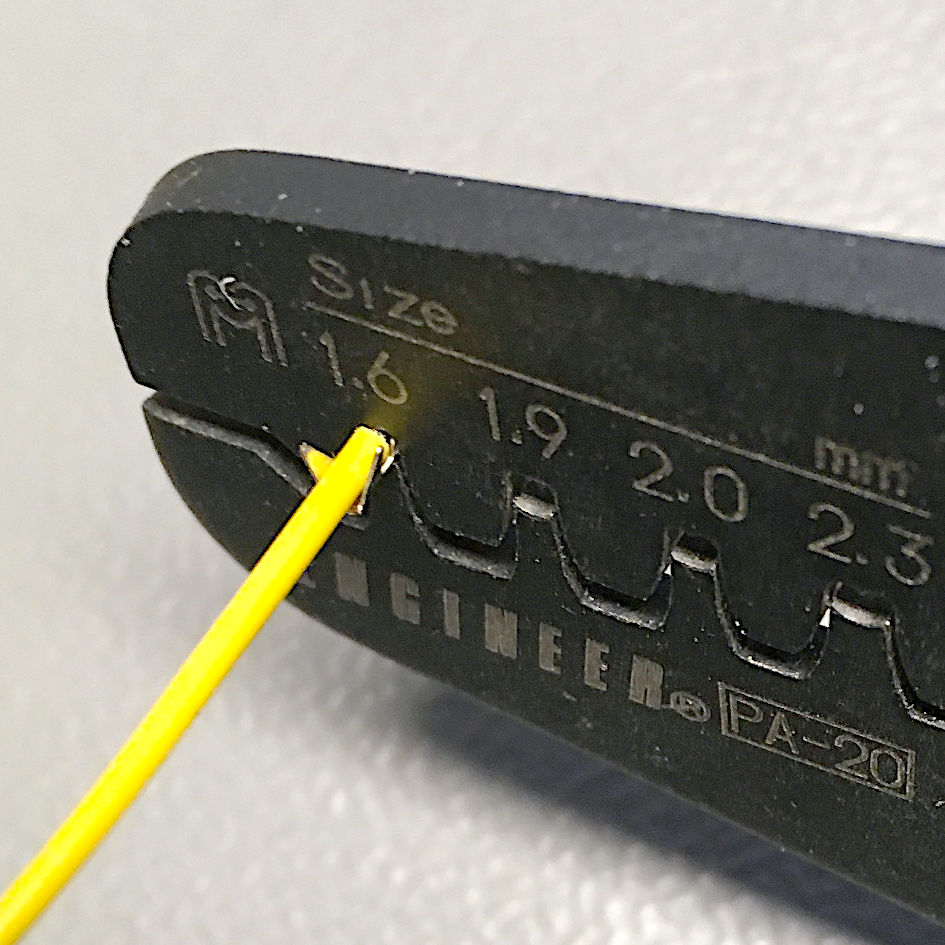
All three crimp tools mentioned before are suitable for this contact and require the same crimping process. Engineer suggests the KK contact to be crimped with the 1.6mm die for the wire crimp and the 1.9mm die for the insulation crimp.
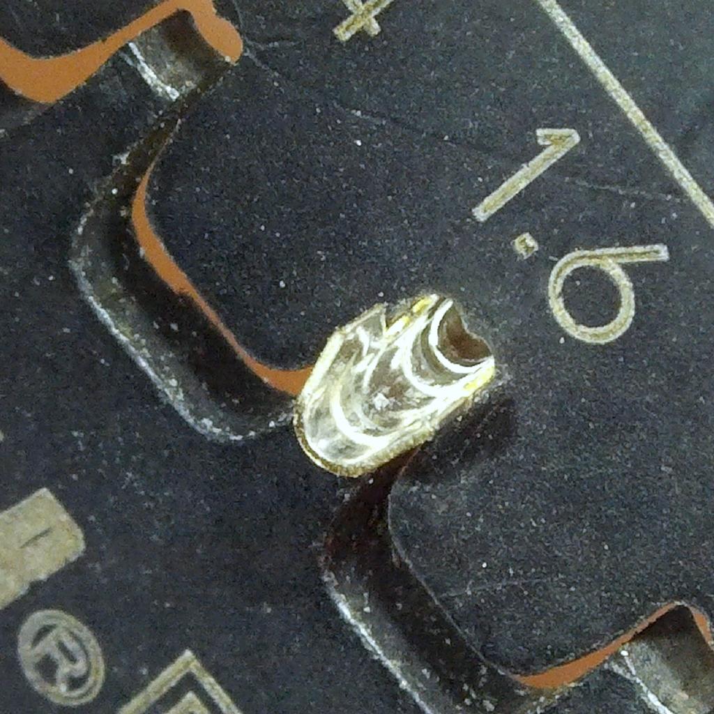
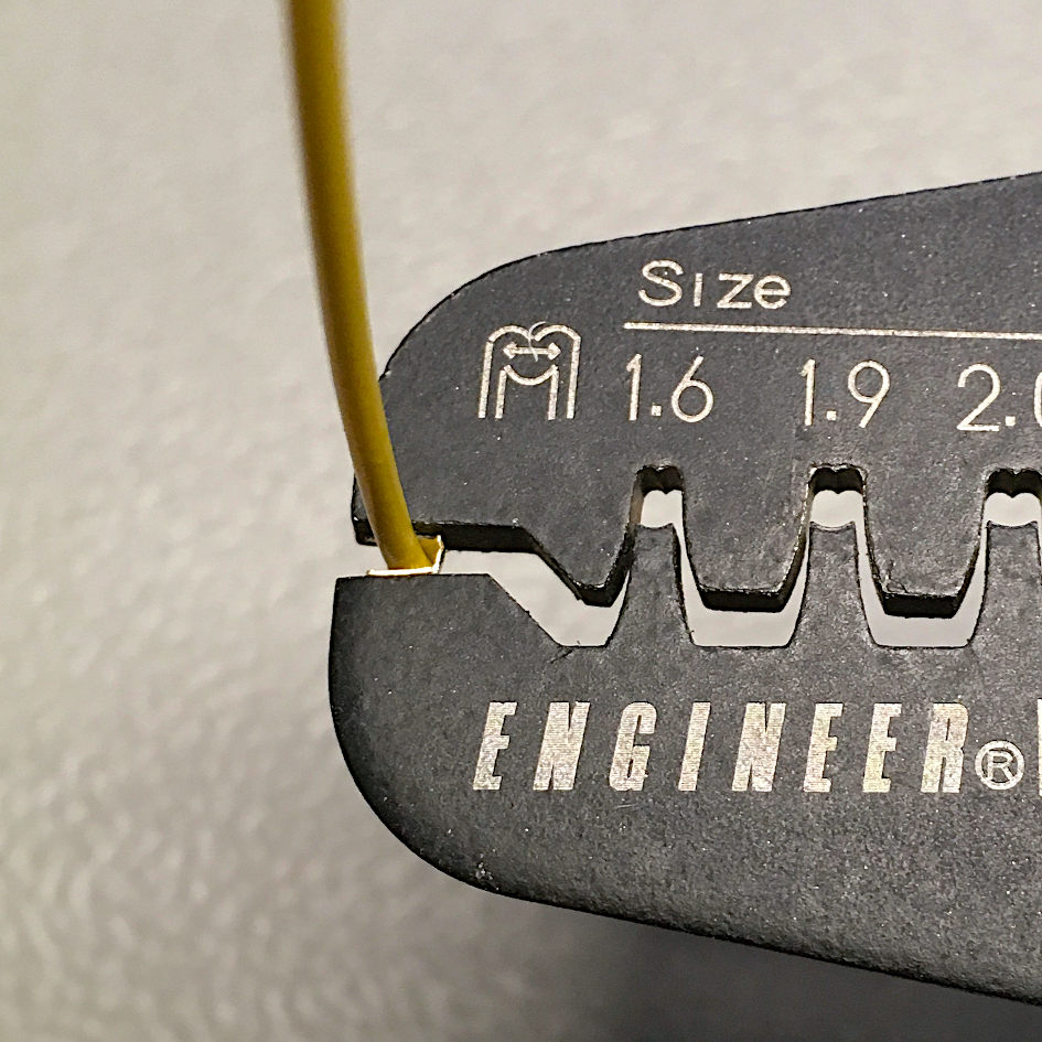
Step 1: Inserting the terminal for the wire crimp
Step 1: Insert the ears for the wire crimp into the 1.6mm die of the crimp tool. Align it, so it is completely inside the tool. Slightly compress the tool to hold the terminal
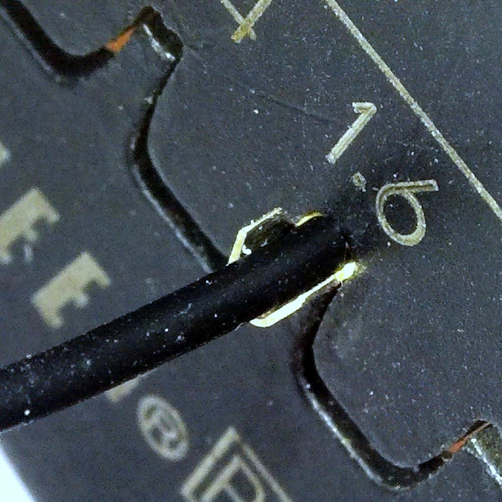
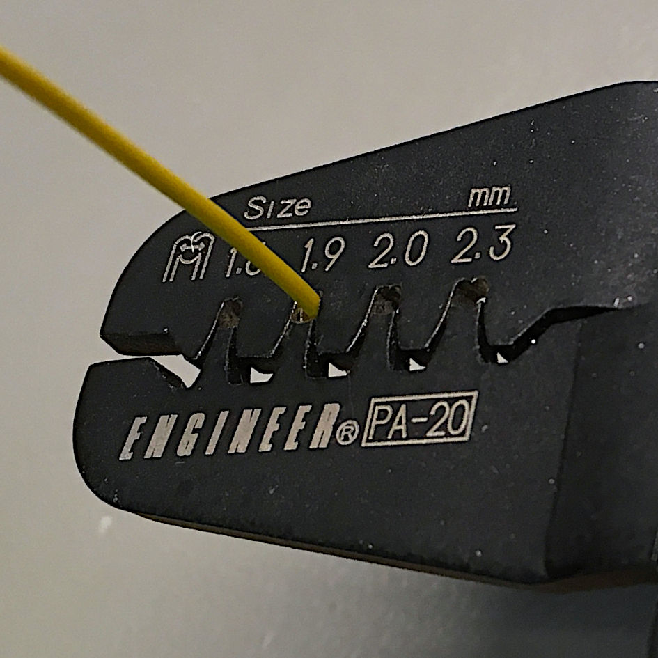
Step 2: Insert the stripped off wire (2mm) into the tool. Align the stripped off part with the terminal. All of the stripped off wire should be inside the tool. Clip off some wire, in case the stripped part is too long.
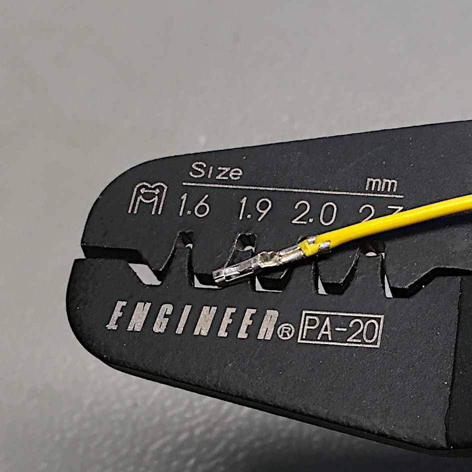
Step 3: Compress firmly (but not over-do it) the tool for the wire crimp and remove the terminal from the die.
Step 4: Insert the ears for the insulation crimp into the 1.9mm die. Align them with the tool, so they are completely inside.
Step 5: Compress the tool, the the ears are bend (forming a B). Less force required than in step 3. If over-done, the terminal might be damaged. Remove the terminal from the tool.
Now, a pull test is required. If you pull the terminal (slightly) with a force, that does not deform the terminal, it shoudl not come off the wire.
Insert the terminal into the crimp housing like shown in one of the previous pictures. They should slide in easily and a slight click will be audible, when the terminal reaches the end-position and is held in place.
Crimping a DuPont Terminal Step by Step (two pass crimp tool)
Neither the PA-09 nor the PA-20 crimp tool are officially announced to be suitable for DuPont terminals, but they do work for theis purpose. The Insulation crimp is not perfect, because it is slightly too wide to slide into the crimp housing. The fix is a slight compression with the flat part of the tool to narrow it a bit.
Step 1: Insert the ears for the wire crimp into the 1.6mm die of the crimp tool. Align it, so it is completely inside the tool. Slightly compress the tool to hold the terminal
Step 2: Insert the stripped off wire (2mm) into the tool. Align the stripped off part with the terminal. All of the stripped off wire should be inside the tool. Clip off some wire, in case the stripped part is too long.
Step 3: Compress firmly (but not over-do it) the tool for the wire crimp and remove the terminal from the die.
Step 4: Adjust the ears for the insulation crimp to be more parallel by slightly compressing them with the flat part of the tool.
Step 5: Insert the ears for the insulation crimp into the1.9mm
1.6mm die (I want to revoke the 1.9mm die, now. I discovered that using the 1.6mm die for the insulation crimp produces better result, at least with the AWG24/0.25mm² cables, that I use). Align them with the tool, so they are completely inside.
Step 6: Compress the tool, the the ears are bent. Less force required than in step 3. If over-done, the terminal might be damaged. Remove the terminal from the tool.
Step 7: the Insulation crimp with the 1.9mm die is slightly too wide. The 1.6mm die works better with the insulation crimp, it seems to make this step redundant.
Step 8: Do not forget the pull test. The crimoped terminal should slide into the crimp housing easily and reaches the end position with the very characteristic click.
Crimping the Molex KK 3.96mm (SPOX) (two pass crimp tool)
The SPOX (3.96mm) connectors is another type, that I use in my projects. The reason is the capability of more current, thicker wires and also the distance (for mains connectors, every 2nd pin is pulled out).
This crimp cannot be carried out with the Engineer PA-09. The dies are 1.9mm for the wire crimp and 2.3mm for the insulation crimp. The IWISS IWS-2820M does not have a 2.3mm die. Here the 2.2mm die can be used for the insulation crimp.
Other than the other die sized, the steps are identialy to crimping the Molex KK 2.54mm.
Step 2: Insert the stripped off wire (2mm) into the tool. Align the stripped off part with the terminal. All of the stripped off wire should be inside the tool. Clip off some wire, in case the stripped part is too long.
Step 3: Compress firmly (but not over-do it) the tool for the wire crimp and remove the terminal from the die.
Step 4: Adjust the ears for the insulation crimp to be more parallel by slightly compressing them with the flat part of the tool.
Step 5: Insert the ears for the insulation crimp into the
Step 6: Compress the tool, the the ears are bent. Less force required than in step 3. If over-done, the terminal might be damaged. Remove the terminal from the tool.
Step 7: the Insulation crimp with the 1.9mm die is slightly too wide. The 1.6mm die works better with the insulation crimp, it seems to make this step redundant.
Step 8: Do not forget the pull test. The crimoped terminal should slide into the crimp housing easily and reaches the end position with the very characteristic click.
Crimping the Molex KK 3.96mm (SPOX) (two pass crimp tool)
The SPOX (3.96mm) connectors is another type, that I use in my projects. The reason is the capability of more current, thicker wires and also the distance (for mains connectors, every 2nd pin is pulled out).
This crimp cannot be carried out with the Engineer PA-09. The dies are 1.9mm for the wire crimp and 2.3mm for the insulation crimp. The IWISS IWS-2820M does not have a 2.3mm die. Here the 2.2mm die can be used for the insulation crimp.
Other than the other die sized, the steps are identialy to crimping the Molex KK 2.54mm.
Molex KK 3.96mm SPOX
Crimping the Molex KK 5.08mm (SPOX) (two pass crimp tool)
This connector type was used for the voltage selector switch in my power supply projects. It required 4 circuits, pulling every 2nd for getting the required distance would have been a 7 way connector, which is not available. The KK 5.08mm offers the required distance for 115V between adjacent pins. Enough with the story, the dies are 1.9mm for the wire crimp and 2.3mm for the insulation crimp.
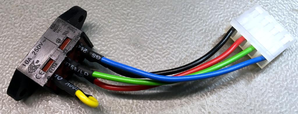
The voltage selectior switch with a SPOX 5.08mm connector
One Pass Crimp Tools (my prefered tools)
The advantage of one pass crimp tools is, that they only require one pass. The ratcheting mechansm provides a persistent execution of the crimp.
The disadvantage is the slightly more complicated adjustment of the crimp terminal within the notch of the tool. You have to place the crimp terminal in the notch in a way, that the wire crimp is fully in the narrower area and