


The First Replacement Power Supply (230V)
The Evil Old Power Brick
One of the first things, you hear, when you restart your C64 hobby is, that the original power supply can be evil. All in a sudden, the +5VDC can output over-voltage, that will immideately destroy your C64. Indeed, this is not very unlikely to happen.
The central part of the original power supply is a transformer with two secondary windings. One is for the 9VAC, the other is connected to a rectifier (2x 1N5400), a smoothing cap (electrolytic) and a linear voltage regulator (3052P).
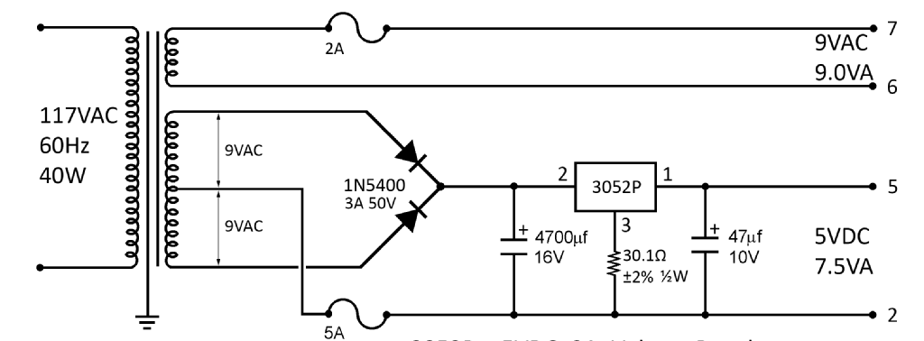
Excerpt from the original schematic (Commodore P/N 902503-02)
The problem with linear voltage regulators is the high dissipated power. If there is an input voltage of 8V (which is a realistic estimation) and an utput power of 5V, there is a voltage drop of 3V over the regulator. The C64 has a consumption of about 1A @ 5V, so the power, that is dissipated in the liear regulator is
Pd = 3V x 1A = 3W
This is almost as much as the power that "heats" the C64 via the +5VDC line. "Dissipated power" means heat. There are also losses in the transformer and also in teh rectifier diodes. As a result, the brick gets pretty warm and smelly. We all remember this.
The heat will dry out the capacitor(s) and will also work out the linear regulator. A failing capacitor might result in an output voltage, that drops below the rated +5V with 50Hz or 60Hz. A failing regulator might short circuit the input voltage to the output. In case the solder joint of the ground pin fails, the same might happen.
According to Adam Caine (twitter: @CommodoreLad), the bad power supplies usually fail after getting warm for a while and not immideately. Just measuring the output voltage after connecting the brick to mains is obviously not enough.
I exercise the original PSUs with a power tester and some load resistors on a heat sink.
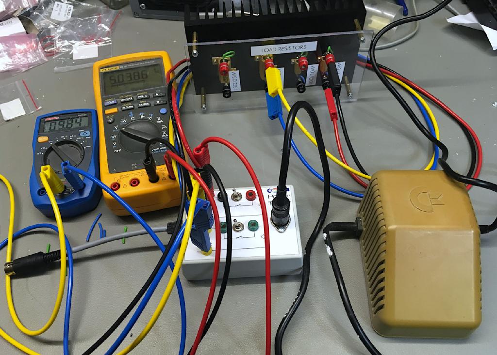
Testing the old power supply
Two multimeters are connected to the power tester. The most interesting one is the one that monitors the +5V. It is slightly higher than 5.0V, which is no problem at all. Without load, a value of +5.3V is not unusual and not bad. With load, 5.2V are still ok. It should not be 5.4V. 4.6V or less is too low. (Annotation: The +5V of a a PC power supply are set to 5.1V - 5.2V.)
The voltage measured on the 9VAC output can be 11VAC without load and are usually higher than 9.0VAC, even with load. This is not considered to be critical, since the voltage is regulated in some way in the C64. A failing 9VDC will either be zero or less than 9V or in the worst case mains voltage (short circuit between primary and secondary coil).
For a proper PSU test, the brick should be stressed (with a load) for a couple of hours. Adam suggests 8hours. More stressing might be thermal cycling: 2 hours on, one hour off, two hours on, one hour off and then four hours on before measuring. This test will reveal dry solder joints with a good likelyhood. Checking the +5V with an oscilloscope might also be a good idea.
The Replacement PSU
My first replacement PSU was created, because I needed one and because I could. It was not planned to release it to be open hardware and it was my first C64 hardware project in 30 years (at least).
My first replacement PSU was created, because I needed one and because I could. It was not planned to release it to be open hardware and it was my first C64 hardware project in 30 years (at least).
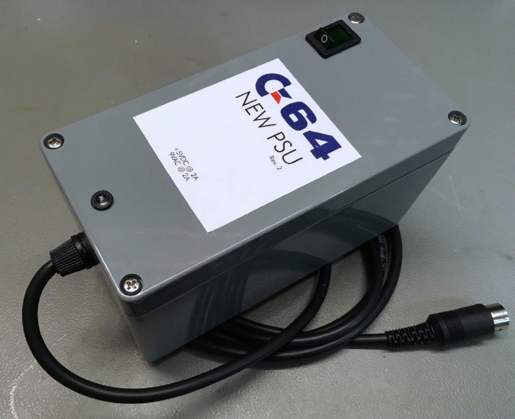
Replacement PSU
The design is straight forward: a transformer with two secondary windings (both 9V/2A), a bridge rectifier, a smoothing capacitor and a DC/DC converter for the +5V.

Schematic of the C64 replacement PSU (Rev. 2)
There are three fuses. One for the primary winding and one for each secondary winding. The (bidirectional) TVS diodes (D2 and D3) are an over-voltage protection of the secondary coils, D1 is a minimum over-voltage protection for the +5V output. In some sources, it is recommended to install a TVS(Suppressor diode) in side the C64: e.g. Retro-Computing, Page 22, so why not installing it direcftly in the power supply? The suggested P6KE6V8A has a breakdown voltage of 6.8V, which is kind of high, so I have chosen a 1N5908 with a breakdown voltage of 6V. Not perfect, but better.
You have probably already noticed, that some cheap telephone chargers or similar small PSUs produce a flicker, when you touch the output (usually the GND). This feels ugly, but it is not harmful to humans. The cause is a capacitive coupling of the isolation transformer between mains and the "secondary" side of these switch mode power supplies. Unfortunately, the power supplies of many S-Video to HDMI converters are not any better and also the PSU of the Pi1541 (a Raspberry Pi based floppy disk emulation) can be like that.
Connecting this kind of device means introducing the flicker to the C64. I have noticed it a couple of times, when touching the user port. I cannort really imagine, that a high voltage, that I can feel is always harmless for the C64! So I decided to put an R/C combination between Ground (GND) and Protective Earth (PE). It is still labeled "Experimental", but it is effective. It is important that C6 is at least a 500V type.
Here is a Youtube video, which partly relates to this kind of problem.
All parts, except the 4-wire output cable are from Reichelt.de.
Please find the project data on my github repository.