


C64 Keyboard
This project is still work in progress!
Actually, I never intended to develop a C64 keyboard.
I would have backed both crowdfunding campaigns, but Indiegogo didn’t allow me to because my credit card requires a security protocol they don’t support.
A few days before Christmas 2024, Retro Fuzion from Australia contacted me and asked if he could donate a case to me in recognition of my “contributions to the Commodore community.” I felt honored and grateful. Based on my previous experience sending parcels to Australia, I didn’t expect the cases before the end of January 2025. But they surprisingly arrived on New Year’s Eve. Suddenly, I needed a keyboard.
Eventually, I might get a CBMStuff Blingboard64, which I’d really like—I’ve already backed their keycap campaign.
Actually, I never intended to develop a C64 keyboard.
- There are already people who have or had Indiegogo crowdfunding campaigns for such keyboards, and I didn’t want to interfere with their business.
- The keycap issue is an ongoing challenge.
- It’s a massive amount of work.
I would have backed both crowdfunding campaigns, but Indiegogo didn’t allow me to because my credit card requires a security protocol they don’t support.
A few days before Christmas 2024, Retro Fuzion from Australia contacted me and asked if he could donate a case to me in recognition of my “contributions to the Commodore community.” I felt honored and grateful. Based on my previous experience sending parcels to Australia, I didn’t expect the cases before the end of January 2025. But they surprisingly arrived on New Year’s Eve. Suddenly, I needed a keyboard.
Eventually, I might get a CBMStuff Blingboard64, which I’d really like—I’ve already backed their keycap campaign.

The wonderful new Retro Fuzion breadbin cases: one clear, one blue.
And that brings us to the next problem: I really want C64-style keycaps for Cherry MX switches. These are so popular and widespread that they’re the natural choice for a modern C64 keyboard. I’m unsure whether I can 3D-print adapters for the original keycaps using my FDM printer. A resin printer is out of the question—too messy and smelly for my taste.
So, I started designing a C64 keyboard without knowing if I could solve the keycap issue—or even what the final keyboard would look like. I only knew there wouldn’t be a flashy RGB light show—that’s for the Indiegogo folks.
I began by taking apart a C64 keyboard and measuring every switch position with a caliper. Thankfully, I have a 30 cm caliper, not just the standard 13 cm one. It’s not long enough for the full keyboard width (385.6 mm), but it worked for most keys. For the few unreachable ones, I measured from the opposite end and adjusted by subtracting half the cylinder’s diameter.
I entered all the measurements into an excel spreadsheet., calculated average distances, and found they were very close to the standard 19.05 mm (¾”, or 1U in keyboard terminology). I used this average to create an evenly spaced layout and remeasured any outliers. My final working delta: 19.04 mm (X) and 19.05 mm (Y). A 0.15 mm difference across 16 keys in the top row is within the usual 0.2 mm tolerance.
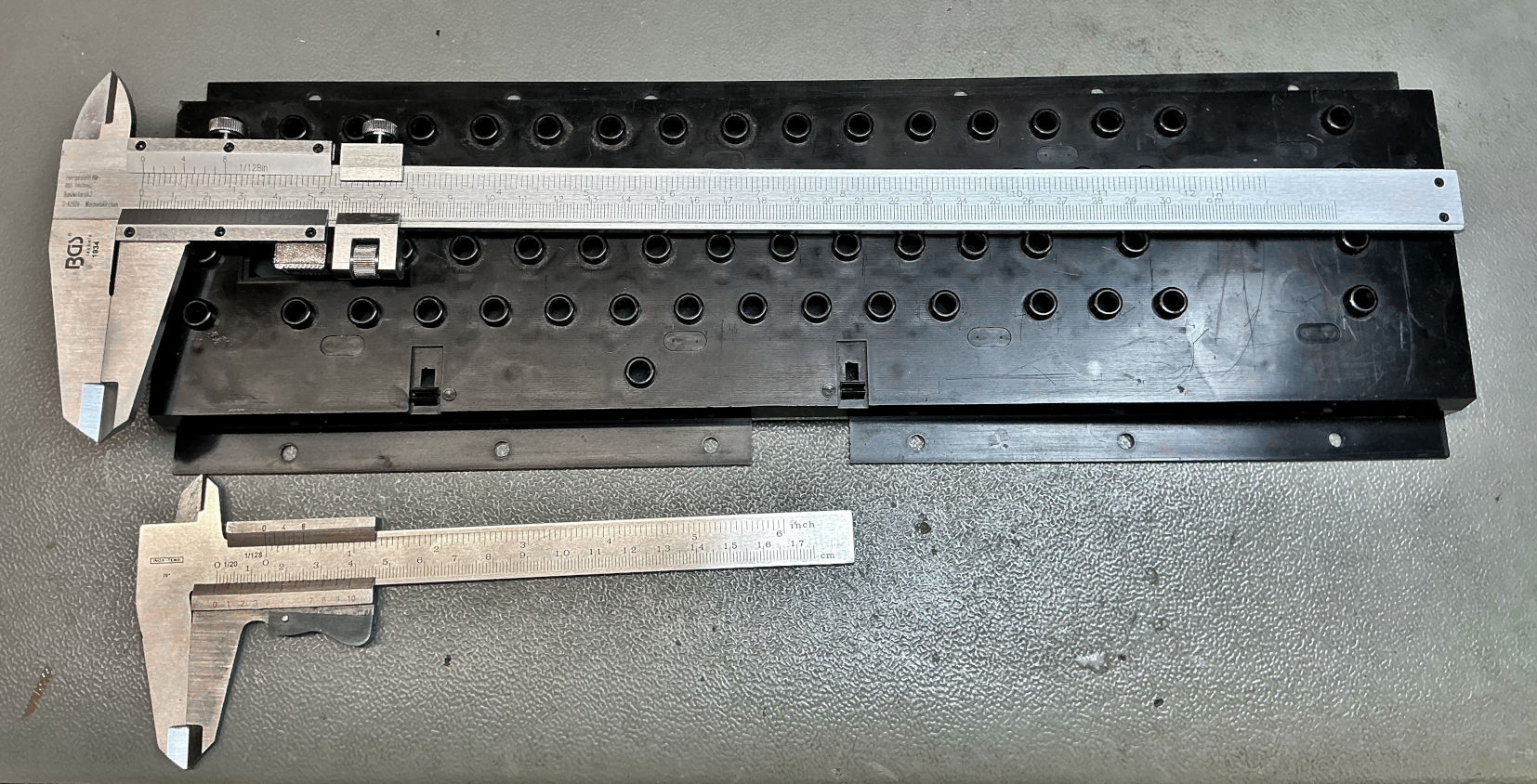
My trusty vernier calipers—standard and extra-long.
With all the positions calculated, I moved on to Eagle to start the PCB design. I began with the keyboard matrix, using the “Attribute” field in Eagle to tag each switch with its corresponding character. I based the matrix on well-known C64 keyboard schematics.
Next, I drew the PCB outline and roughly placed each switch, entering their exact positions via device properties. Then I measured keycap sizes: standard 1U is 18x18 mm; most wider keys are 1.5U (27.1 mm), RETURN is 2U (37 mm), and the spacebar is a whopping 9U.
Since I couldn’t find a 9U spacebar, I planned to use three switches: 1U + 7U + 1U = 9U.
To accommodate both original Commodore keycaps (with adapters) and modern Cherry MX keycaps, I created overlapping switch positions. I always try to maximize flexibility for users of my projects..
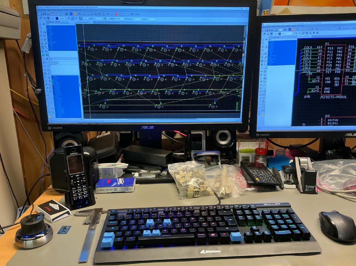
Eagle design of the C64 keyboard
I noticed enough space on the board for an Arduino Pro Micro and a 16-bit I/O expander (PCF8575) with I²C, which connects to the matrix. The Pro Micro was chosen for its USB HID capability, so the keyboard could function as a USB device for VICE.
Years ago, I made a keyboard controlled kernal switcher for the C64 that’s mostly unknown—but one of my favorite creations. It lets the user choose one of eight KERNALs using RESTORE + number keys and can reset the C64 with a longer RESTORE press. This could be integrated into the new keyboard.
Programmable keys could simulate input via the I/O expander.
I also needed a non-latching Shift Lock. Cherry MX switches are momentary, so I measured how much bouncing occurred. Most bounce happened during release (about 100 µs). I used an RC circuit to debounce it and added a toggle flip-flop using a 7474 D-FF. The left shift is controlled via a transistor, inspired by the SX64’s keyboard (I/O board).
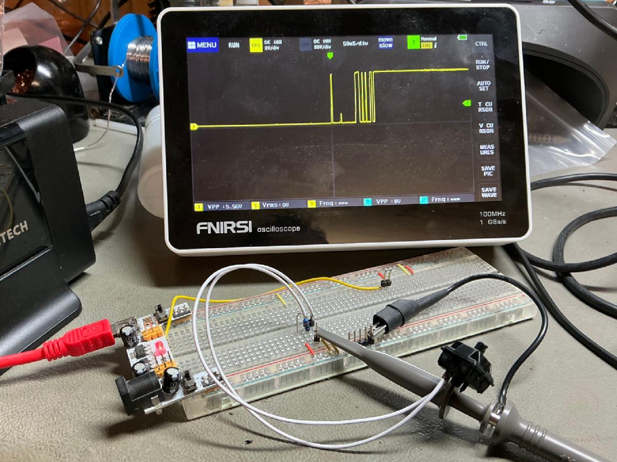
Bouncing of the switch at release
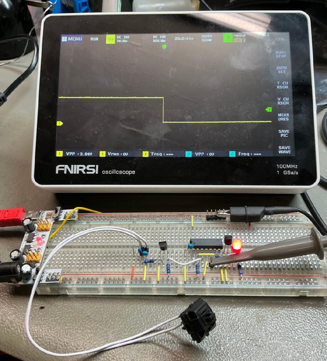
Shift lock circuit on a bread board.
I haven't tried out any circuit on a bread board in my job, but since the keyboard PCBs will be pretty expensive, I thought, it might be better. It was fun, too.
With just this circuit, the keyboard is usable. The optional Pro Micro adds:
The keycaps are a major problem. The best keyboard is hard to use without. Generally, it will be possible to use the keyboard with original keycaps plus a wobbly adapter pin, but that is not the way of my choice.
So, I have researched methods of printing blank Cherry MX keycaps at home. Well... some investments are required.
Dye sublimation is a way to get the letters on the plastic. That requires an inkjet printer, that is capable of printing dye sub ink. The ink will be printed on a special paper. With heat and pressure, the ink will be transferred to the keycap. I have seen people doing that with a hair iron with adjustable temperature. I think, this method is nice, especially, since you can use the printer for normal printing, too, but it will take several minutes per keycap.
The next candidate for solving the keycap problem is laser engraving. This seems to be faster and probably more accurate, since you don't have to place a paper upside down on the keycap, but have to adjust the position of a laser projection of the outline on the keycap. The downside is the requirement for a 1300€ investment, the laser engraver (IR laser, which makes it capable of engraving plastic and metal).
Since I see myself engraving my logo or whatever on everything I have in the future, I have decided for buying a LaserPecker LP3. This is working with a galvanometer and mirrors for positioning the laser beam, so it is faster and provides a higher resolution than the laser engravers, that have a moving laser head, like a 3D printer or CNC machine.
Before printing comes drawing. And before drawing comes scanning the keycaps.
With just this circuit, the keyboard is usable. The optional Pro Micro adds:
- KERNAL switcher
- USB HID keyboard
- Programmable keys
- RGB strip interface (WS2812B)
The keycaps are a major problem. The best keyboard is hard to use without. Generally, it will be possible to use the keyboard with original keycaps plus a wobbly adapter pin, but that is not the way of my choice.
So, I have researched methods of printing blank Cherry MX keycaps at home. Well... some investments are required.
Dye sublimation is a way to get the letters on the plastic. That requires an inkjet printer, that is capable of printing dye sub ink. The ink will be printed on a special paper. With heat and pressure, the ink will be transferred to the keycap. I have seen people doing that with a hair iron with adjustable temperature. I think, this method is nice, especially, since you can use the printer for normal printing, too, but it will take several minutes per keycap.
The next candidate for solving the keycap problem is laser engraving. This seems to be faster and probably more accurate, since you don't have to place a paper upside down on the keycap, but have to adjust the position of a laser projection of the outline on the keycap. The downside is the requirement for a 1300€ investment, the laser engraver (IR laser, which makes it capable of engraving plastic and metal).
Since I see myself engraving my logo or whatever on everything I have in the future, I have decided for buying a LaserPecker LP3. This is working with a galvanometer and mirrors for positioning the laser beam, so it is faster and provides a higher resolution than the laser engravers, that have a moving laser head, like a 3D printer or CNC machine.
Before printing comes drawing. And before drawing comes scanning the keycaps.
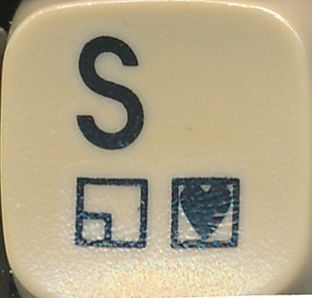
Scan of a C64C/G keycap
The surface isn’t flat, so scanning distorts the image. Image processing didn’t work.
Luckily, I found the font: ITC AvantGarde LT Medium / AvantGarde CE. PETSCII characters were easy enough to recreate.
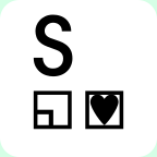
Inkscape drawing of the S keycap.
Not perfect clones, but close. DSA keycaps have a different shape, but they’re flat on top—good for laser work. PBT plastic was chosen for its dye-sub resistance and nice texture.
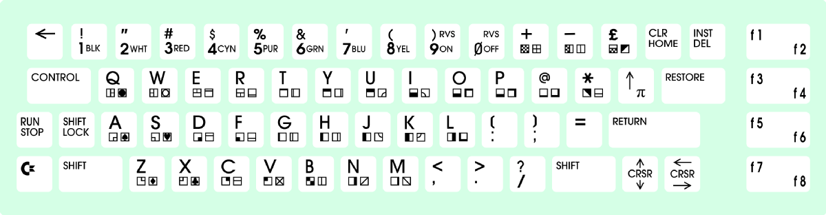
The complete keyboard drawn in Inkscape.
Blank DSA profile keycaps (for Cherry MX switches)
When reading about the keycaps, I had to learn quite a couple of things:
1. There are many different shapes/profiles of keycaps.
2. some profiles have different shapes depending on the row, some have equal shapes in every row.
3. For dye sublimation, you have to have a more heat-resistant type of plastic. PBT (polybutylene terephthalate) is suitable for that, ABS is not.
I did not decide, which "printing method" I would be using, when I have ordered the blank keycaps, so I ordered PBT ones, which I found ot that I liked them. The surface feels nice.
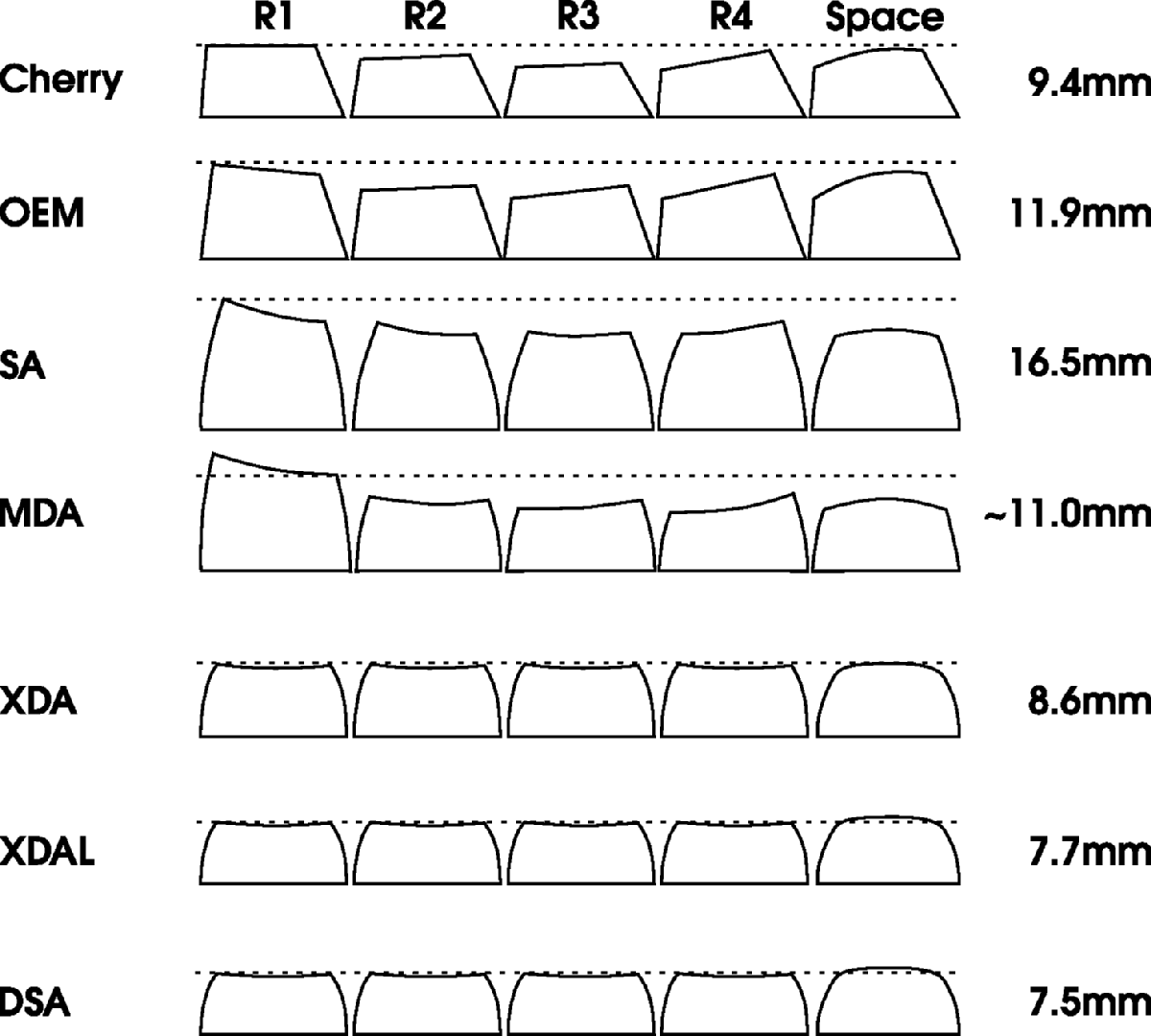
Some keycap profiles
The previous image shows some of the available profiles for keycaps and their approximate heights. It is a compilation of multiple sources on Internet. Further, it is not an accurate drawing, but a graphic approximation of the actual keycaps.
I have ordered the keycaps some time before I decided for the printing solution, that I will make use of. DSA keycaps to have a good availablity, the top surface is not very curved, so there is neither a great distortion of the text on a curved surface, nor a focus problem for the laser.
I have ordered the keycaps some time before I decided for the printing solution, that I will make use of. DSA keycaps to have a good availablity, the top surface is not very curved, so there is neither a great distortion of the text on a curved surface, nor a focus problem for the laser.
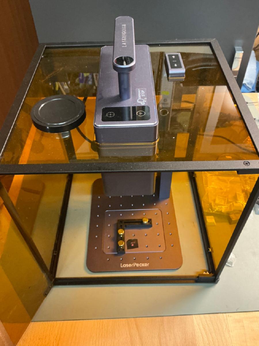
LaserPecker LP3 laser engraver
When the laser engraver arrived, I have tried to engrave some sample objects, which came with the LP3, but I could not wait until the next morning to try it out on the actual keycaps, so I have done a couple, before I went to bed.

The first keycaps, that I have engraved
Actually, I have worried a bit about a consistent positioning of the text on the keycap, but that is not really hard. I have made the size of the PNGs, that I use for engraving identical to the size of the top of the key cap and there is a laser frame projected in the size of the actual picture. If it is any misalignment, this frame goes down the sides of the keycap, quickly.

Aligning the print on top of the keycap. It is easy, but don't forget it!
There are some dangerous aspects to laser engraving. Maker's Muse on Youtube has made a good video (do not click the URL if you are not ok with Youtube collecting your data) about it, which I would recommend. Mainly, I see a risk for your eyes and those of the people and pets around. Don't engrave without proper eye protection and the safety hood. It is an IR laser, which is invisible. The next aspect are the fumes of the things you actually burn with the laser. I have noticed a pretty decent amount of precipitate on the inside of the safety hood. The exhaust fumes are transported out of the box without filtering. There is only a fan.
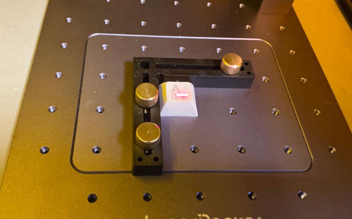
Laser engraving a keycap. The red dot is just a marker.
Engraving one keycap only takes a few (maybe 15) seconds (excluding the time for selecting and aligning the text). Actually, engraving is not, what it really is. It does not have any depth on the keycaps. It is just darkening the plastic.
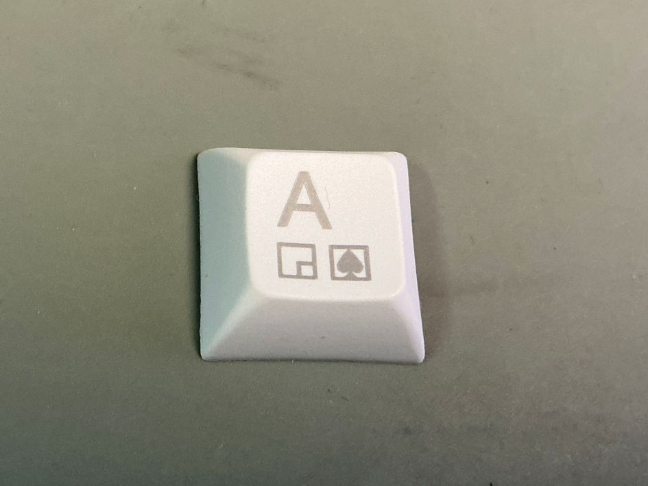
A laser engraved keycap
The result is a dark grey, but not black text. I have tried to mix in some kind of toner, like pencil dust, crayon or putting a flimsy paper on top, but that only caused problems and did not produce a darker "print".
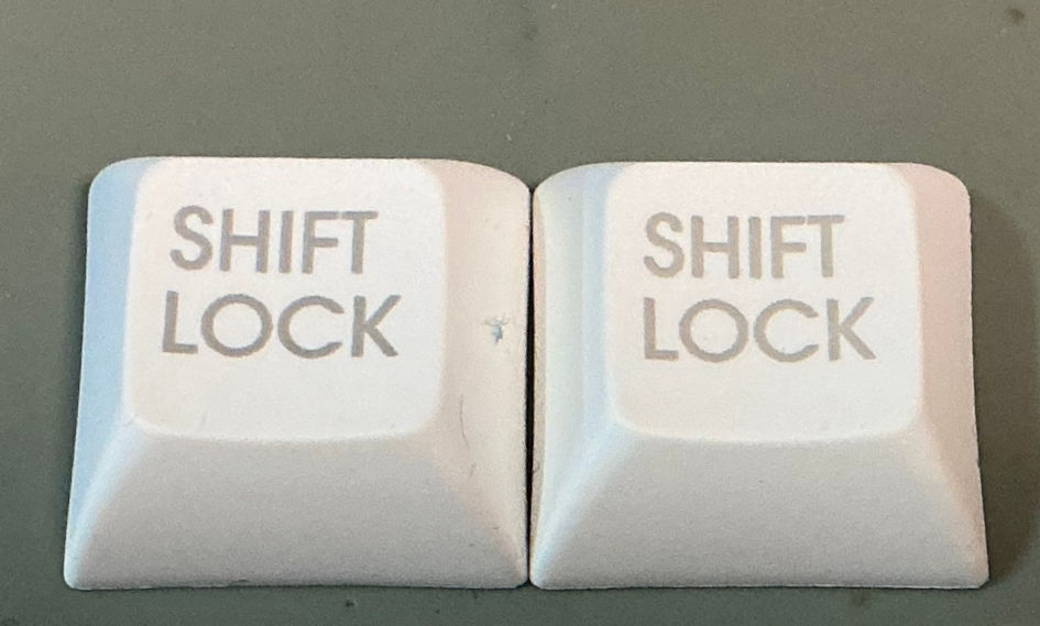
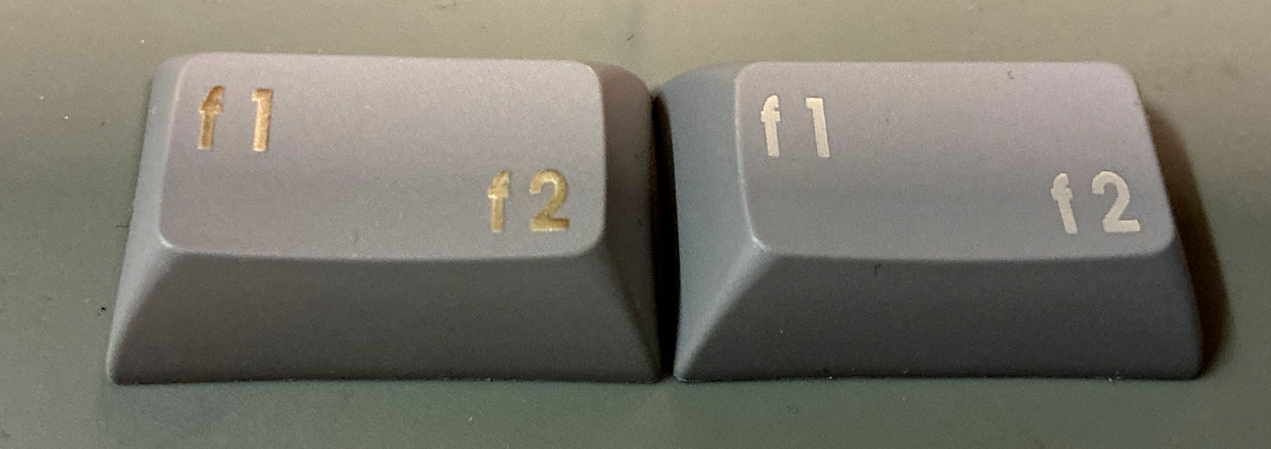
Comparison of the shift lock key with different print parameters
Finally, I have found some parameters, that produce a slightly darker text on a white keycap. Actually, I have even used less power for engraving.
Grey keycaps with different speeds and power
Grey keycaps can be laser engraved as well. The result is a relatively light text, which is also readable. More power does not always help, as can be seen from the previous image. The text looks charred and even boils up.
Lasering transparent keycaps did not produce a decent result, yet.
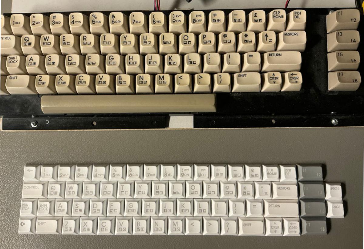
The complete set of keycaps vs. the original keyboard.
I have improved the keycap text, that was not accurate enoug:
● pound
● up arrow/pi
● all f-keys
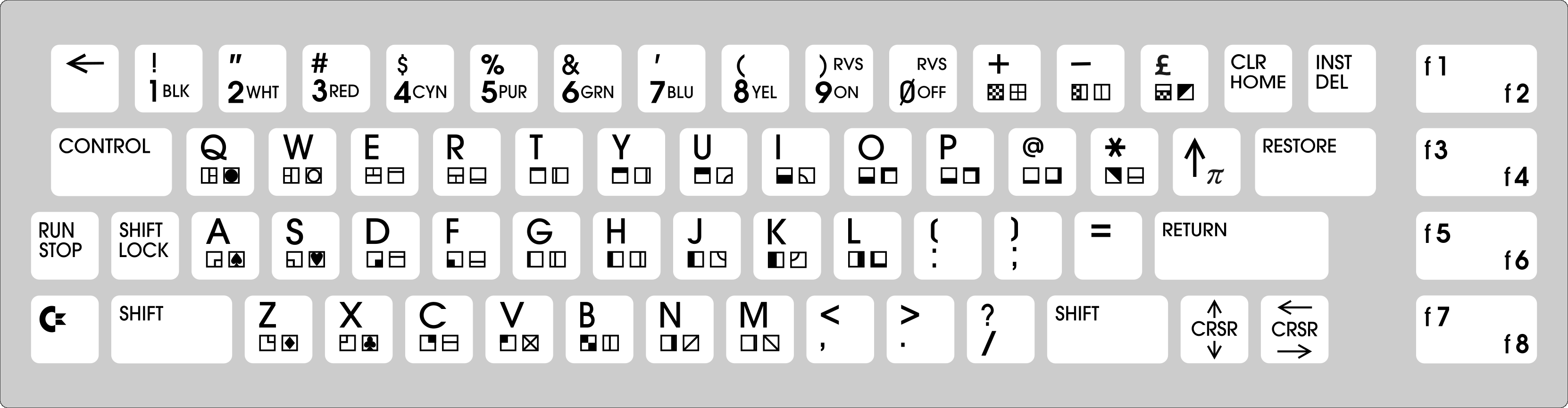
Final keycap legend
The keyboard and keyboard connector PCBs arrived and I could hardly wait to assemble them. SMD components first, of course. The footprint of the mechanical switches was already tested in another project, so, there was no problem to expect.

Mounted switches with stabilizers
Even the stabilizer footprints worked well. So, that was a big relief, since I have never handled any stabilizers before.
The 5-pin switches also align very well. there is no need for a mechanical keyboard mask.

Keyboard with keycaps and keyboard frame
Now, the keyboard frame had to be designed. The first prototype worked well with the breadbin case, but...
I had to try the keyboard with every case type, that I had and that resulted in several design iterations and a heap of prototypes to discard. First, I have reduced the height of the frame, so that the keys don't stick out as much, especially when installed with the C64C case. Then I have found a C64C case with strange keyboard brackets, which collided with the sides of the frame. The original plastic frame of the keyboard does not have real sides, but I have decided to have them to give the structur more stability.
Then I have tried the keyboard in a C64C clip case. There was a requirement for the frame to provide something for the clips to clip to. At least two more iterations!
Finaly, I have had a collision of my keyboard connector constrction with the frame in the C64C with a short board. One more iteration :-)
Oh, I didn't mention the keyboard connector, yet. The goal is to have a connection, that does not require cable crimping and that is easy to make. I came up with a little PCB, that had an IDC connector and a female connector for the keyboard pin header on the C64 board.

Keyboard cable with keyboard cable PCB instralled

Keyboard with frame and cables installed in a breadbin
The keyboard cable works perfectly and is an easy build. All it takes is a vice to crimp the IDC connector.
The keyboard works without the pro micro, so I could test the keyboard matrix in a real C64.

Keyboard test on my trusty "C64 nude", an easy to access short board with an acrilic cover.
Everything works like desired.
Now, I have started writing the firmware for the pro micro. It already plays a nice melody on the piezo buzzer :-) Unfortunately my paid projects are quite demanding right now, so this might become a lengthy project...
What’s next:
- Design a 3D-printable keyboard frame ✔
- Finalize PCB layout ✔️
- Order prototype PCBs ✔
- Assemble prototype ✔
- Write Pro Micro firmware
- Test everything
- Document or iterate