


Constructing a 3D-printable Replacement Connector
Some weeks ago, a friend has bought this beautiful old machine, he could not even test is, because it came without a mains cable.
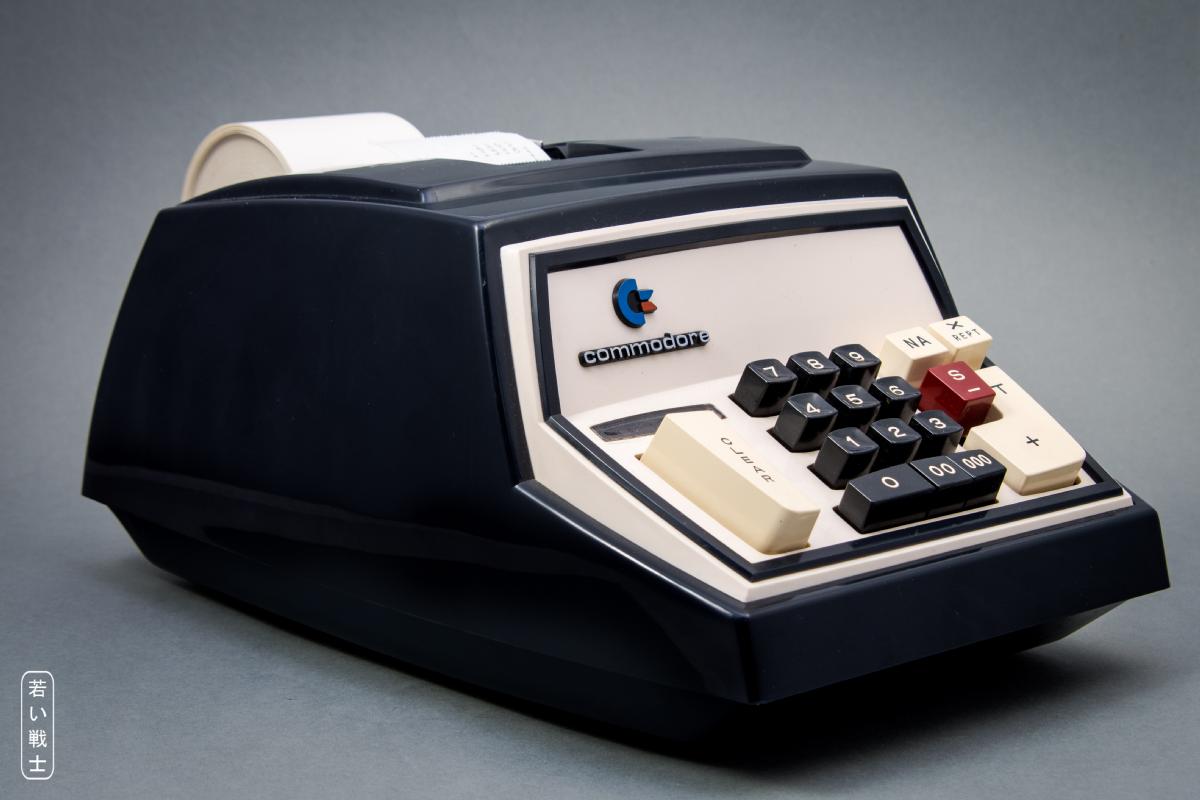
Commodore 202 adding machine
In case you are interested in more pictures of this machine, check this category on Wikimedia Commons: Commodore 202. I have taken pictures of the adding machine and donated them to Wikimedia Commons.
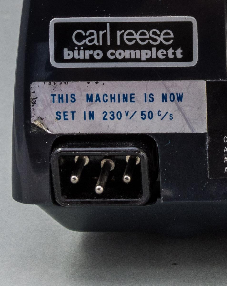
"Japanese Calculator Connector"
What I did find out is, that the mains connector is a "Japanese Calculator Connector", but that's it. The don't seem to be available anymore. So, I thought of a way to make a mains connector for the good old Commodore to test it.
WARNING: In most countries, mains connectors need certifications, so I cannot recommend to construct, print and use a mains connector. It might be illegal and not covered by any insurance to use such a connector. It might be harmful to your life or result in a fire hazard.
The first thing, that I did, was measuring the pins. The diameter is 2.7mm. None of the crimp terminals, that I had in stock, was fitting exactly. I have found some TE connectivity terminals, but they were nowhere in stock and I would have to order a couple of thousands of them to get them produced. The closest, that I have in my assortment boxes were 3.5mm bullet connectors (I think, these are used in French cars), which I have bought from AliExpress ("120pcs/set 3.5mm Brass Bullet Connector Terminal Male & Female with Cover") a year or so ago. I sure had to bend the terminals a bit, which would not be acceptable for a series production, but this will just be a prototype, so this is ok.
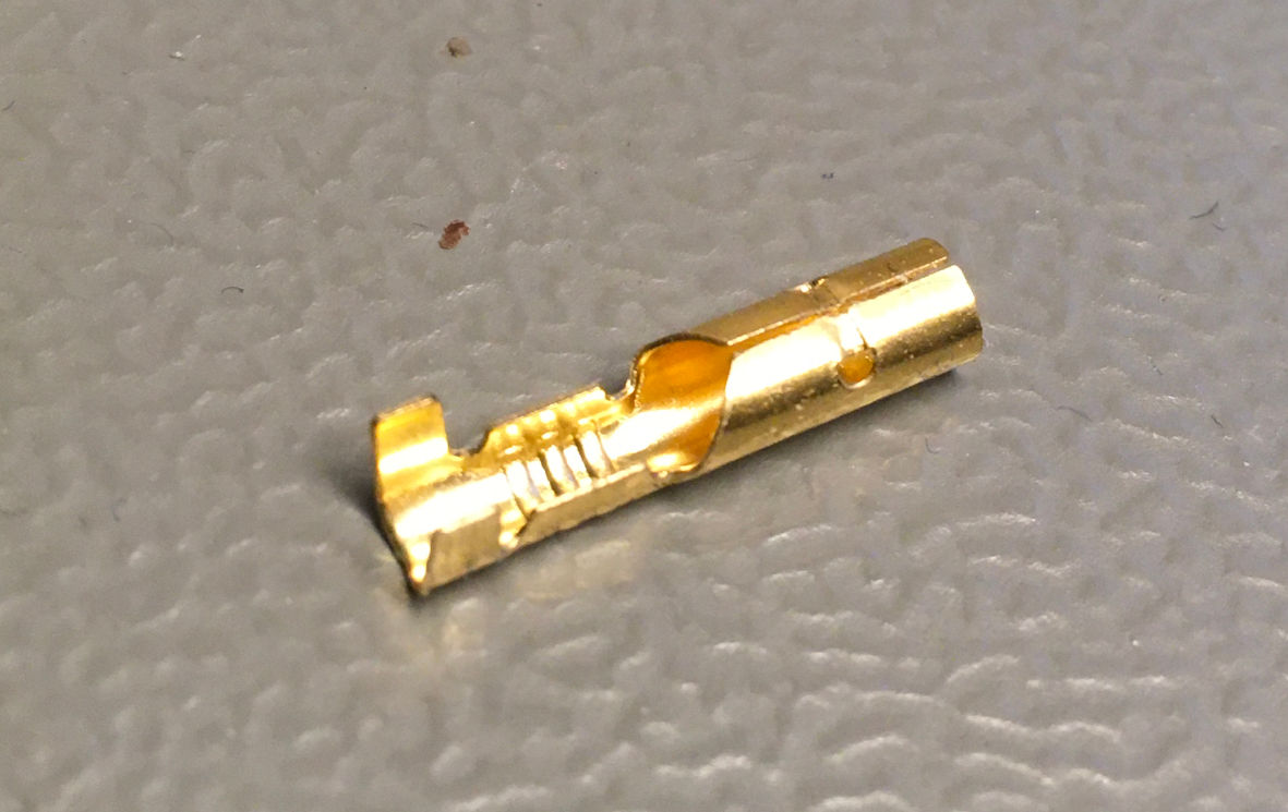
3.5mm bullet connector socket/female terminal
I have crimped these connectors with an IWISS SN-28B crimp tool to a 3x0.75mm² (AWG 20) mains cable, bent the crimp terminals a bit to reduce the contacting diameter and tried it out "in situ". (For cable making/crimping, please refer to this page).
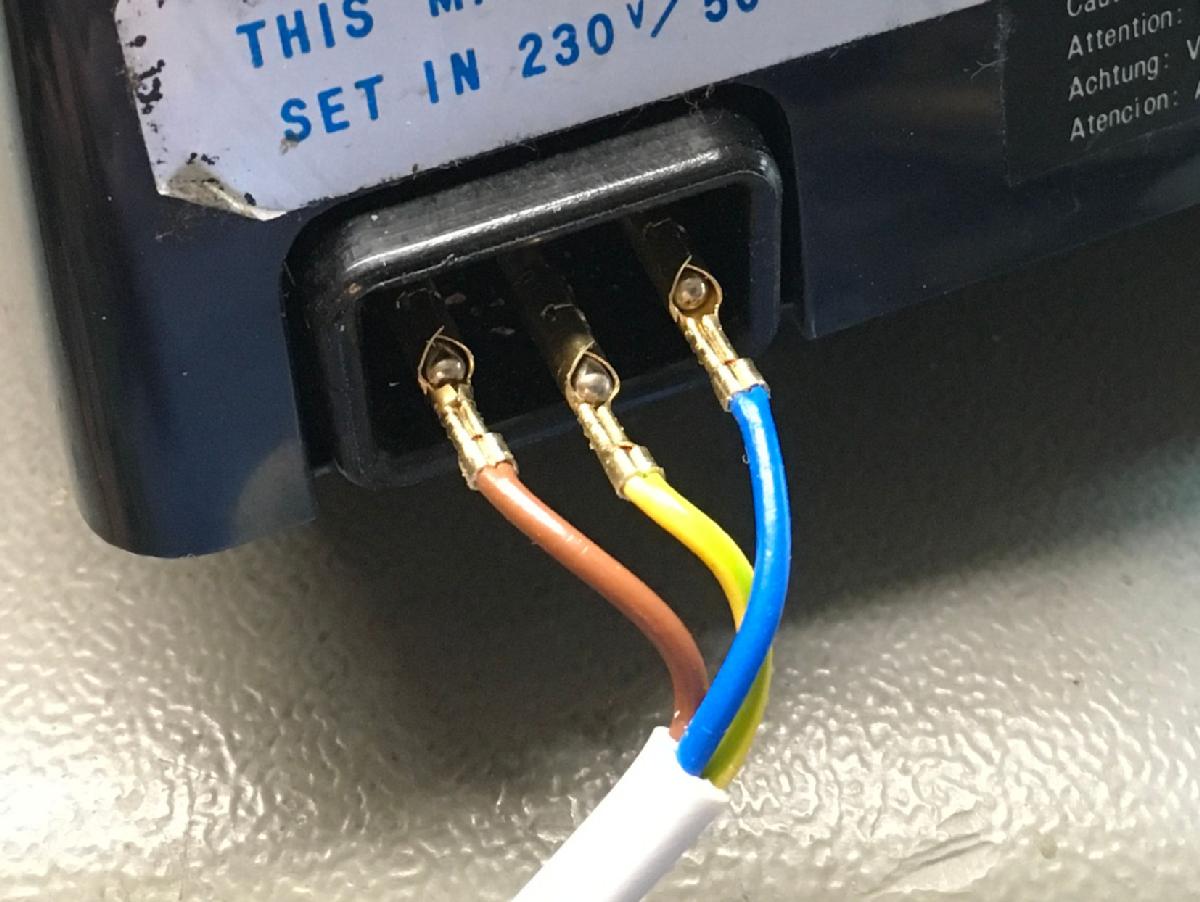
Testing the (already bent) crimp and the crimp terminals
Again: Do under no circumstances connect this to mains voltage. This could be lethal!
Results:
1. The crimp with this tool is suitable.
2. The bent terminals make a good contact with the pins of the Japanese calculator connector
Next was measuring the connector of the Commodore 202 and drawing it with Fusion 360.
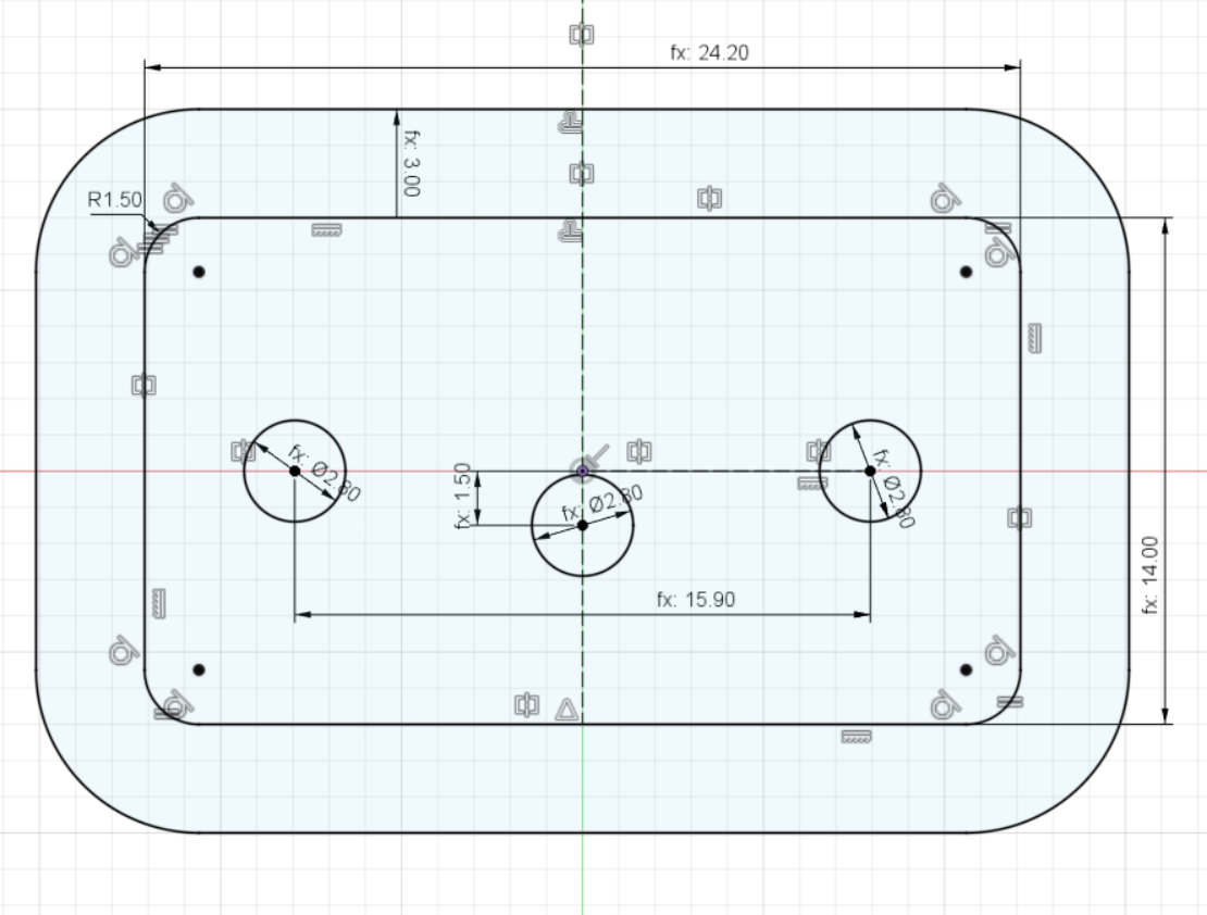
Drawing of the Japanese calculator connector
From this drawing, it is easy to generate a 3D model of the connector. It just requires measuring the pin lengths and the depth of the connector to then extrude the drawing. I have also measured the already crimped terminal (! you want to model the final measures to fit those into the connector) and made a 3D model. If you are not familiar with 3D construction (yet), it is no witchcraft. It is based on 2D drawings like above and those are basically extruded to the required lengths/heights to create a three-dimensional body.
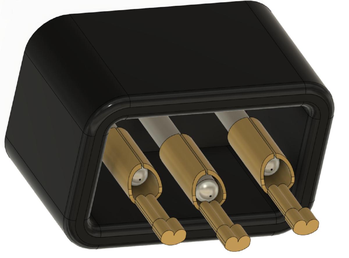
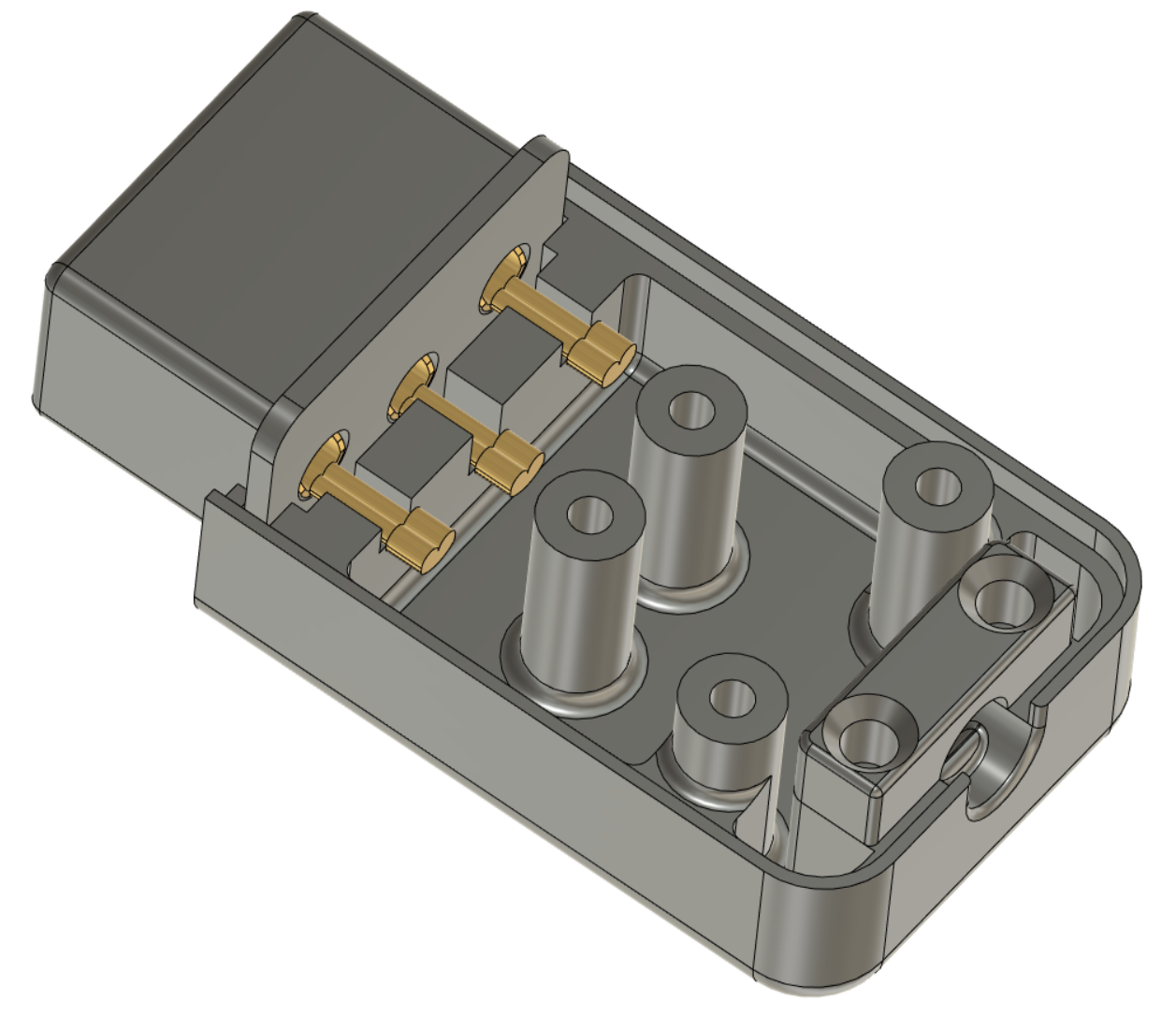
3D model of the mains connector and the crimp terminals
The next important consideration was the alignment of the pins. The middle contact (protective earth/PE) is 2mm longer than the other pins. The purpose is to keep the connection engaged while pulling out the plug after hot (L) and neutral (N) already get disconnected. So the crimp terminals should all be aligned to the PE crimp terminal. This is easier to construct, anyways.
The connector consists of four printed parts.
1. the connector base
2. the top shell
3. the bottom shell
4. the strain relief
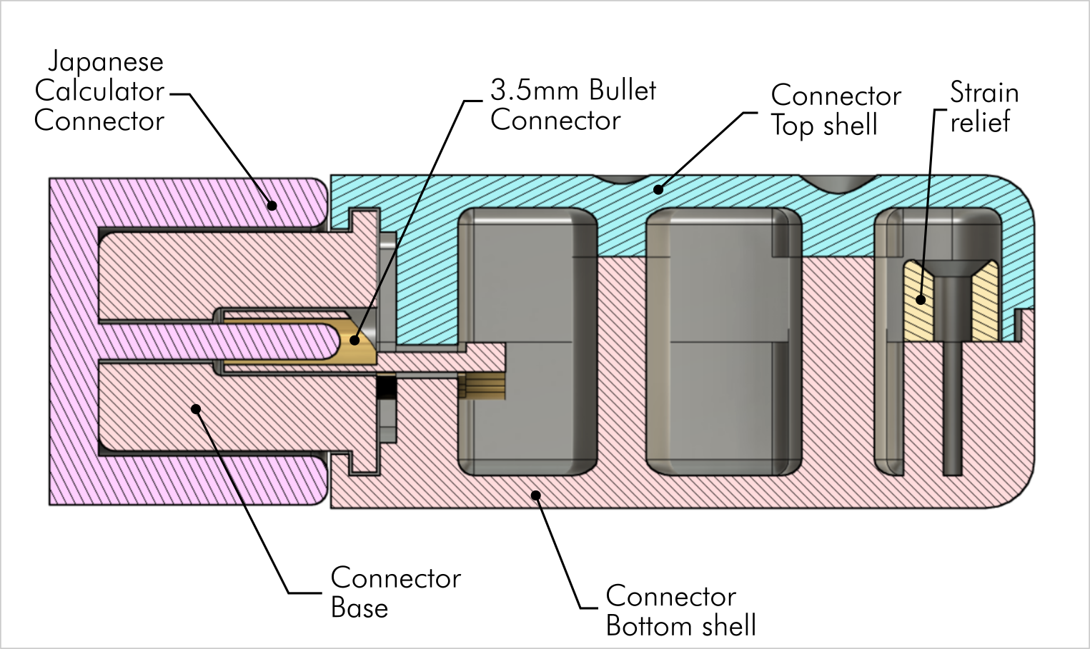
Cross section of the 202 mains connector
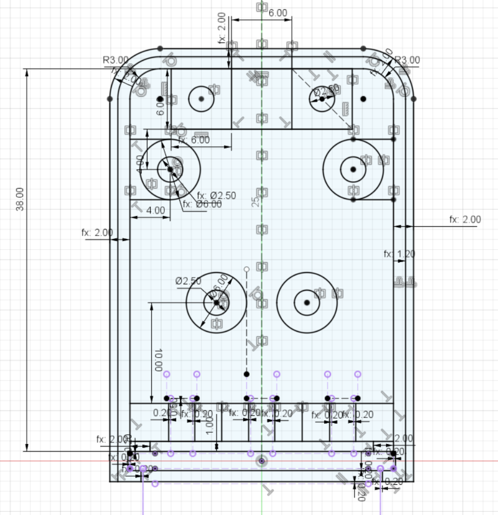
Drawing of the bottom shell
For the printability, the connector base, which holds the crimp terminals is separated from the bottom shell. It is best to print it vertically, lying on the insertion side for the crimp terminals, since overhangs don't print well and the drills require some precision. The tolerances are tight (0.2mm). The connector base is a tight fit in the top and bottom shell. It might be required to slightly file the rim around, depending on the printer and the filament.
The strain relief is an extra part. This function is important, you don't want the mains cable to be pulled out of the connector.
For a better assembly, the screw posts on the bottom shell are long, thus the screws are from the top side of the connector. This is not looking perfect, but I wanted the cable to be installed in the bottom shell. Using black screws with black filament (I use Prusament PLA Jet Black - I think, the prints are more precise) might make it look a bit better.
It would be possible to screw from the bottom, but that would require a pretty different construction:
1. the strain relief is screwed to the top shell
2. the crimp terminals are turned 180°, so that the crimps are facing up
3. the "wall", which clamps the crimp terminals is higher, so the PE terminal can be held securely
The crimp terminals are clamped by top and bottom shell. This way, they stay in position, even in case the alignment is not perfect (they are not perfectly round anymore).
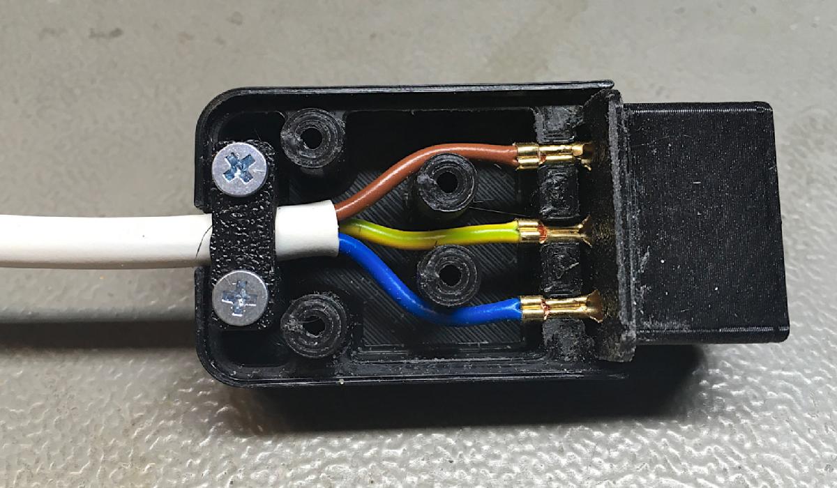
Connector with base, crimp terminals, bottom shell and strain relief
Two screw posts might have been enough, I have made four. The I don't want it to be any unstable. The length of the bottom/top shell (43mm) is also generously measured. I have learned not to underestimate the bending radius of a (AWG20) cable. I don't want it to be a very tight fit. The PE cable should go straight between the two middle screw posts, while the L and the N cable should go around those.
Connector with base, crimp terminals, bottom shell and strain relief and cable
An additional strain relief could be achieved by installing a cable tie around the cable (firmly pulled) inside the connector. This is not shown in the above picture. The picture also shows, that the connector body (top & bottom shell) is not much too long considering the required space for a cable tie like mentioned before.
The screws are DIN 7982 C2.9x9.5H (countersunk head screw for sheet metal - 2.9mm, 9.5mm long), the cable has a diameter of about 5mm.
The screws are DIN 7982 C2.9x9.5H (countersunk head screw for sheet metal - 2.9mm, 9.5mm long), the cable has a diameter of about 5mm.
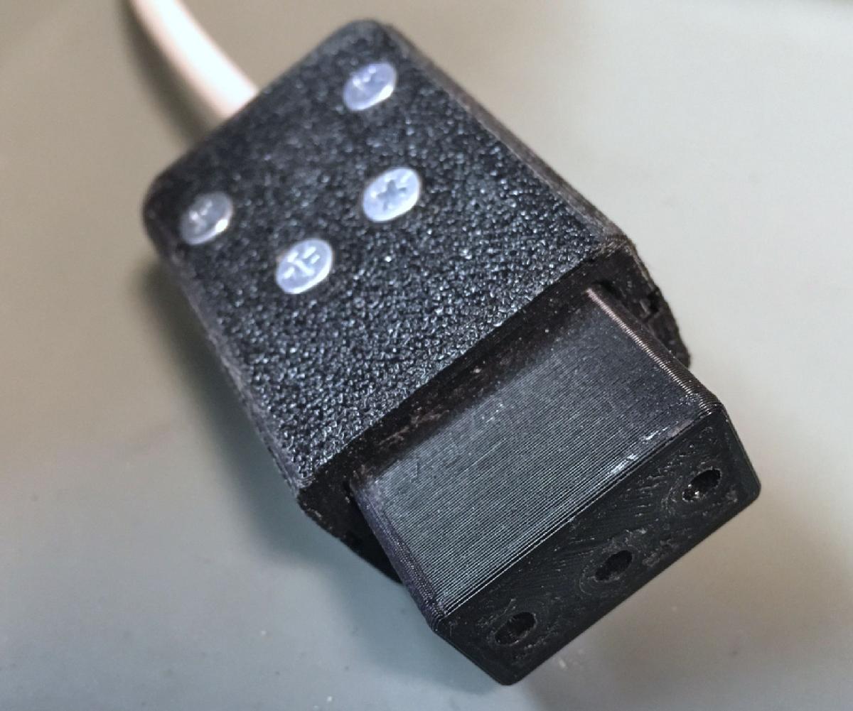
Front view of the connector
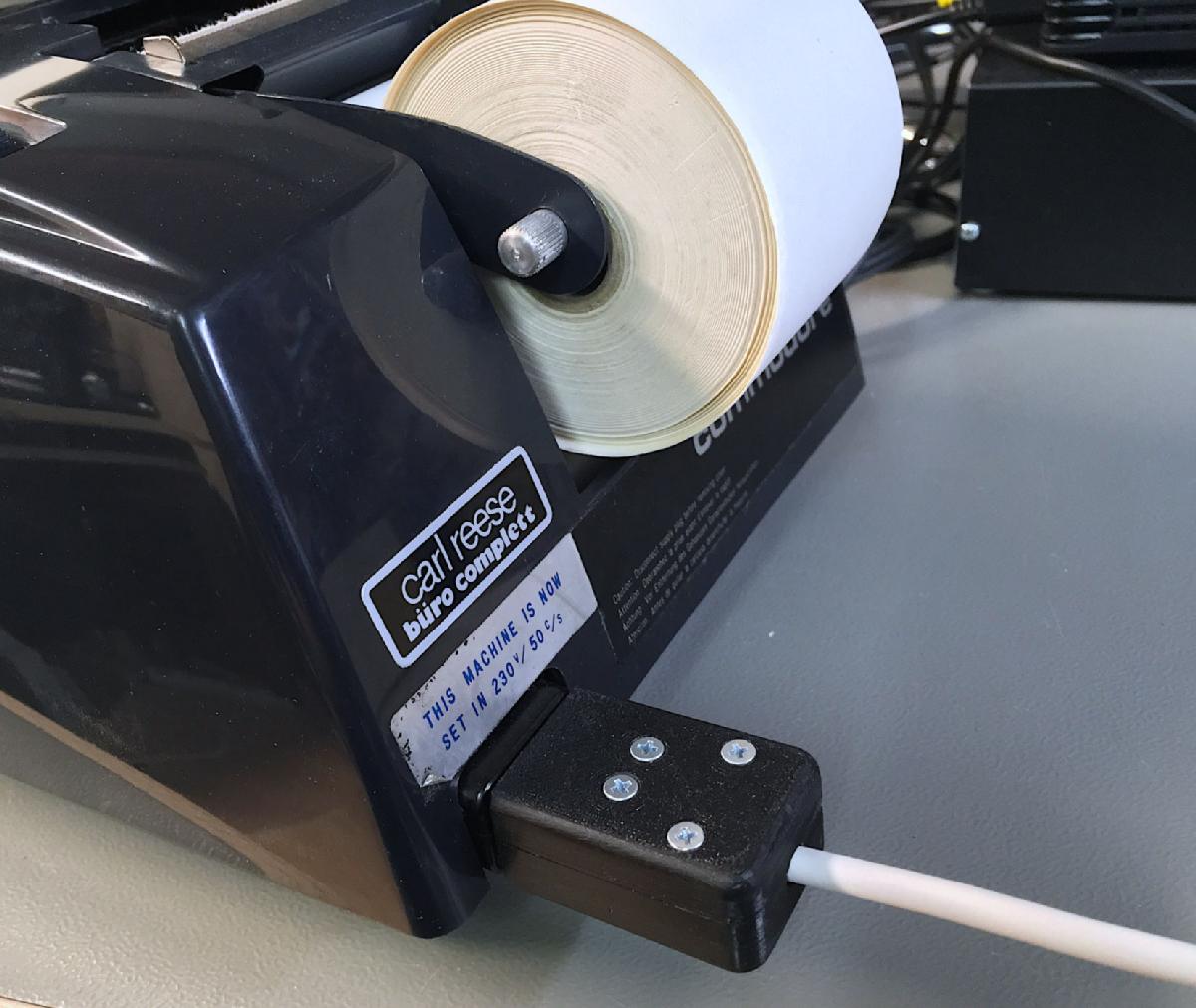
Commodore 202 with the inserted mains cable
I do not encourage you to build and use such a cable due to the potential harm for your health and property. It might also violate regulations for mains connectors/cables, since this is not a certified product. The damages caused by the use of such a connector are most likely not covered by any insurance. I have warned you and I am not liable for what you are doing.
The design file and the STL files can be found here: https://www.thingiverse.com/thing:5227423