


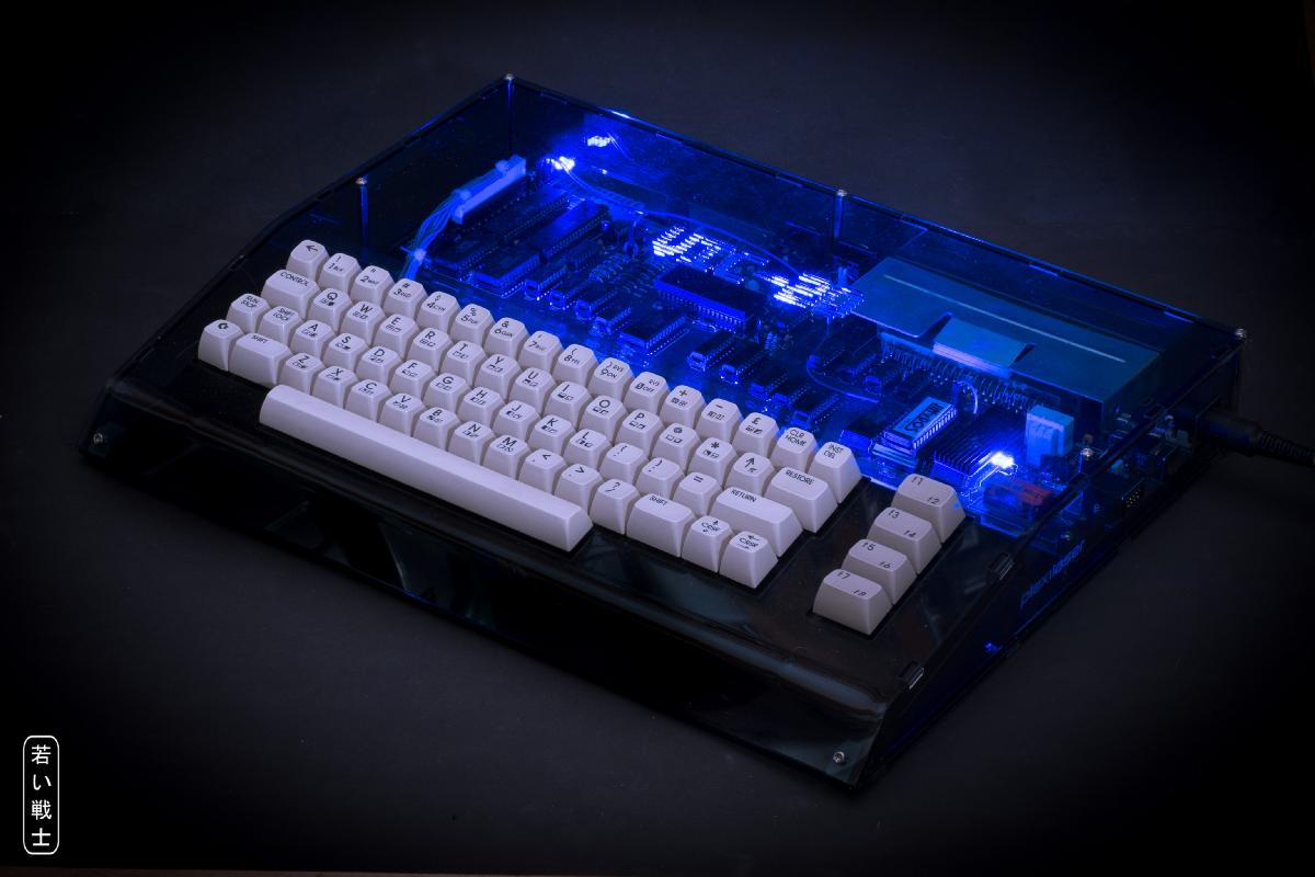
VickyTwenty S-Video Mod
The VickyTwenty is a clone of the VC-20CR (CR = cost reduced). It is built from original MOS chips, new ICs and components and a new PCB, which was made by Rob Taylor (aka PeepoUK). The MOS Chips are still available (6502 and 6522), the VIC might be a bit harder to get. I have bought them from AliExpress.
In general, the video quality of the VIC-20 is not the greatest. The two-prong VIC-20 is quiote a bit better than the CR version (with the C64 DIN power jack). An S-Video mod, like it is described at sleepingelephant.com (denial Wiki) or at hackup.net.
The VIC chip has a separate luma (pin 3) and chroma pin (pin 2), and both signals are mixed to get a composite video output. An S-Video mod is a pretty small modification.
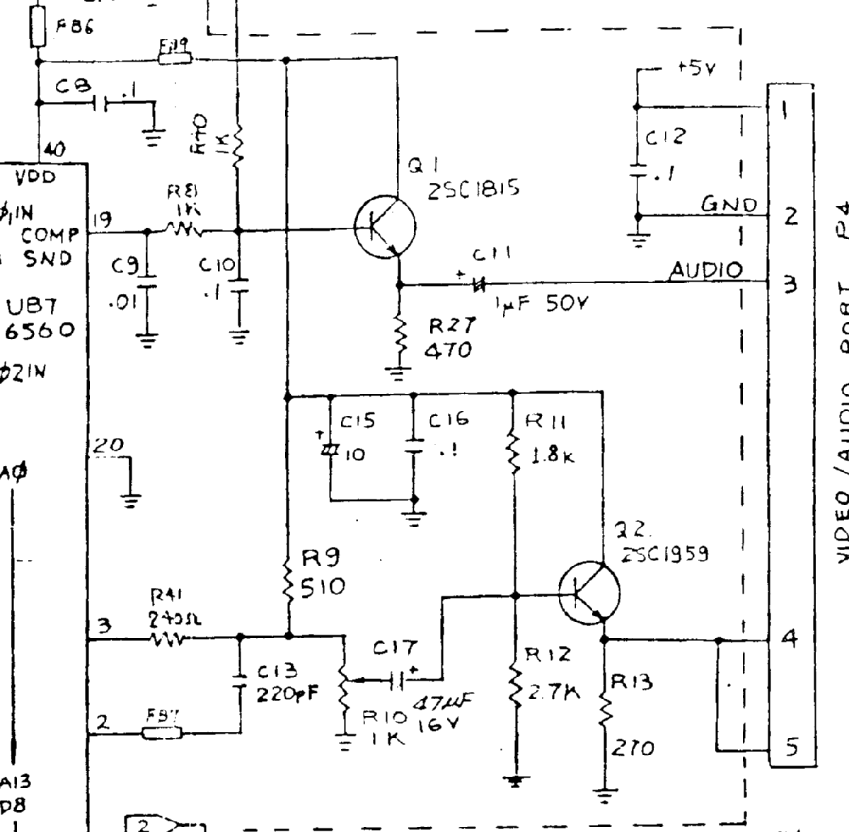
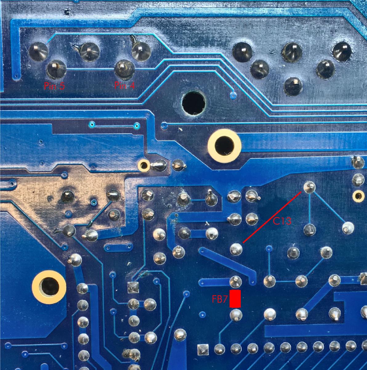
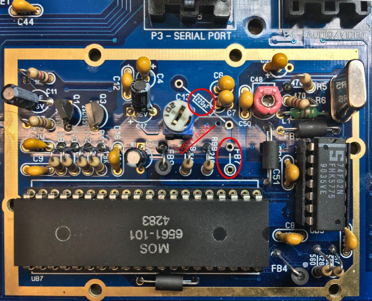
The original video circuit (VIC-20CR)
FB7 and C13 are mixing chroma and Luma to get composite video. For the S-Video Mod, FB7 has to be replaced with a 100nF (5mm pin grid), C13 has to be removed and a 75Ohm resistor has to be added. Pin 5 has to be separated from Pin 4 (both are originally Composite Video).
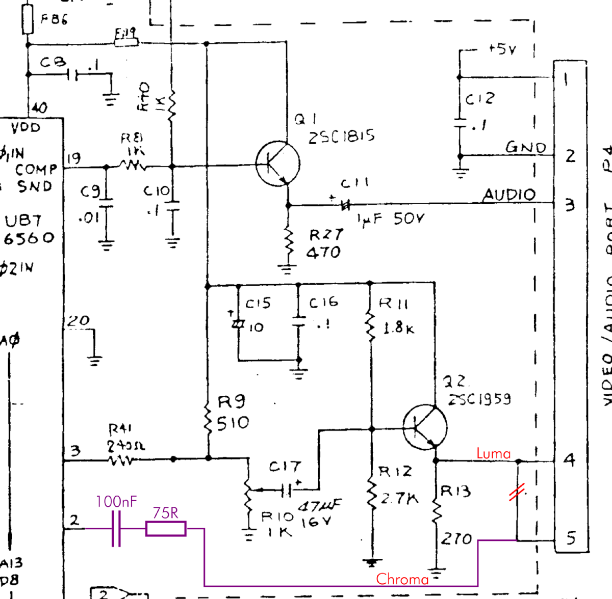
Video Circuit after the S-Video Mod
After the S-Video Mod, Pin 4 of the Video (DIN-)jack is Luma, and Pin 5 is Chroma. Due to the modified connector pin out, the S-Video mod requires a modified/dedicated cable or an adapter. Find my VIC-20 A/V-Adapter here.
The cloning of the VickyTwenty is very good, but not 100% the same as the VIC-20CR Board (ASSY No. 250403): The vias are "modern", which means the drill has a smaller diameter and the via is covered with solder stop.
For this reason, a little 1mm hole has to be drilled to place the 75R resistor. This is the difference between the VickyTwenty S-Video Mod and the Mod of a VIC-20CR.
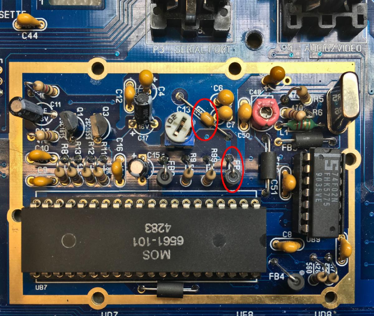
FB7 and C13 have to be removed
The situation on the solder side
FB7 and C13 is now removed and a hole for the 2nd pin of the 75R resistorte (1mm) is drilled
The hole should be approximately in the middle between the solder pad and the closed via, which is too small to be used as a solder pad.
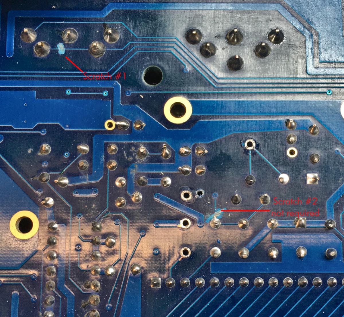
Scratched traces
The first scraced trace is between pin 4 and pin5 of the A/V connector. The 2nd scratch is according to the sources mentioned before, but since the via cannot be used for the 75R resistor, it is not required.
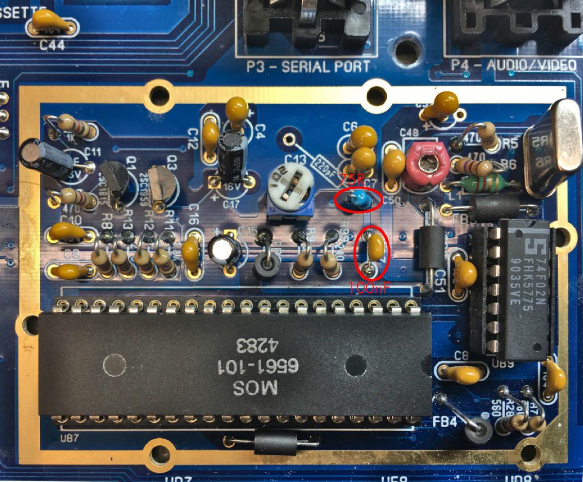
100nF cap and 75R resistor installed
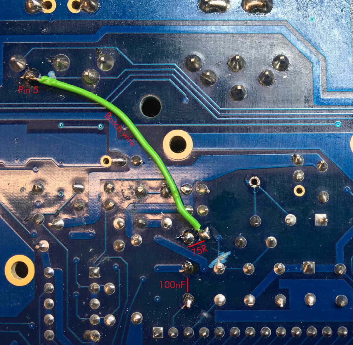
Modification of the solder side
The (green) botch wire connects the 2nd pin of the 75R resistor (which is put through the drilled hole) and pin 5 of the A/V jack. It carries the chrominance signal, now.
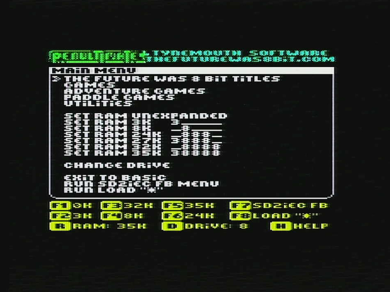
The quality improvement of the S-Video mod is quite impressive. Some of the traditionally bad color combinations demonstrate this more than the BASIC screen of the VIC-20/VickyTwenty:
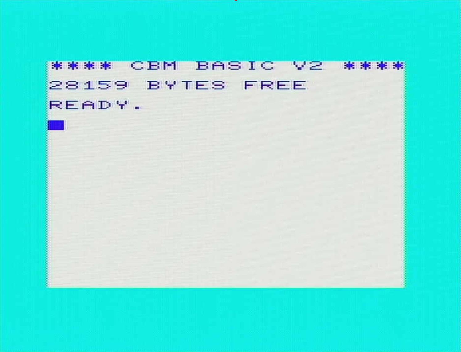
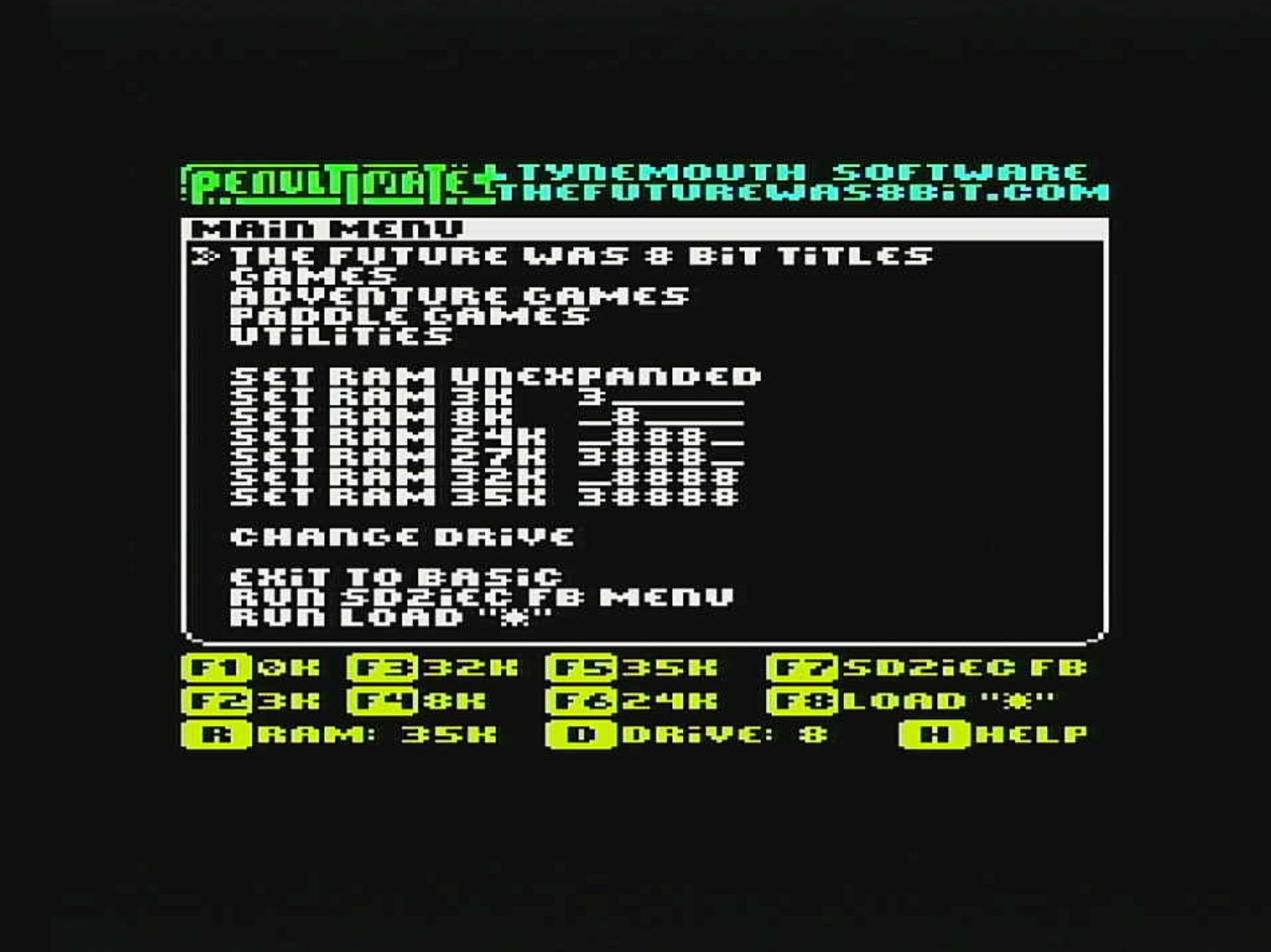
BASIC screen with composite (original)
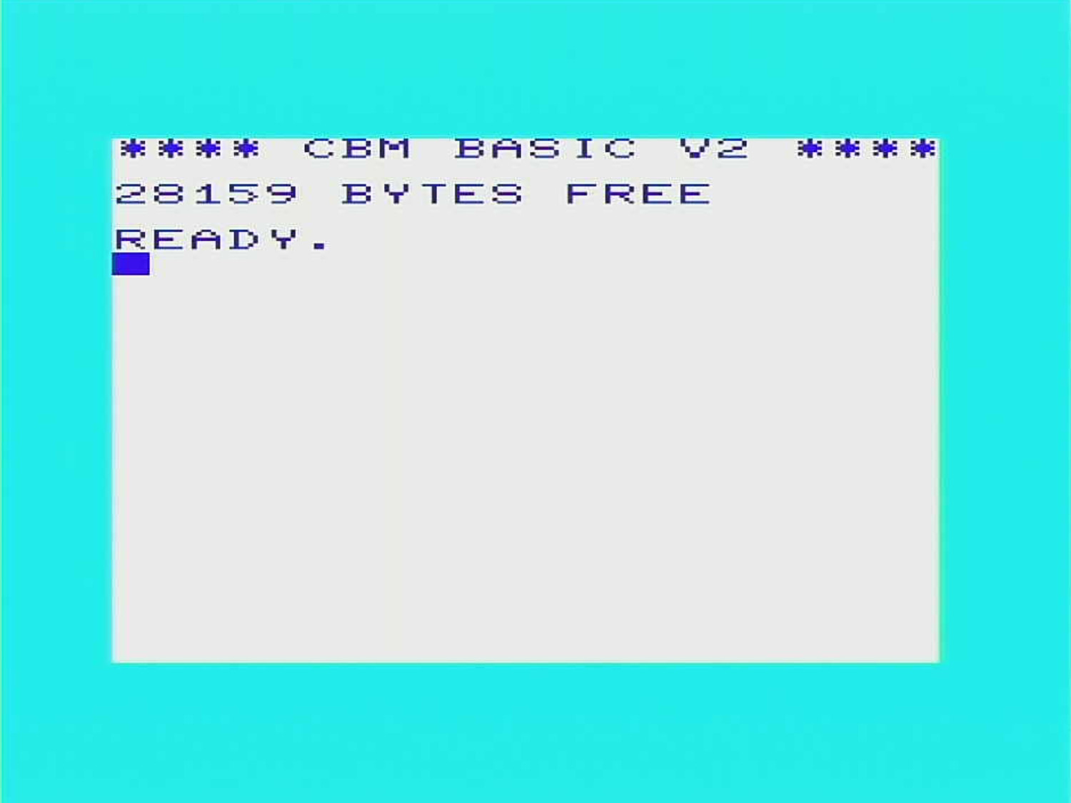
BASIC screen after the S-Video mod
Same with S-Video mod
Especially the green and cyan title looks much better after teh S-Video mod, while the white on black looks pretty ok in the original.
Finally Donkey Kong. Much better!
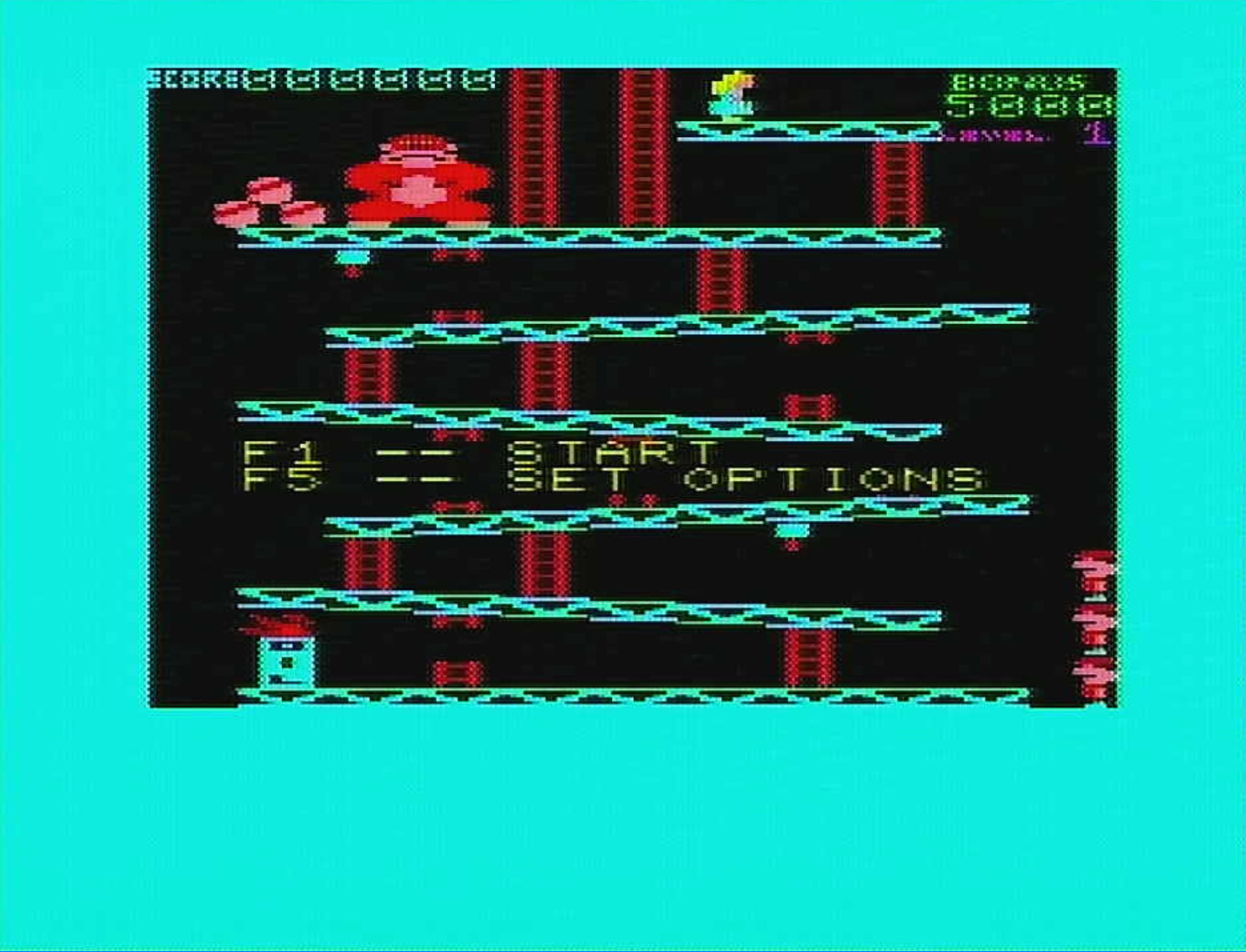
Donkey Kong with composite (original)
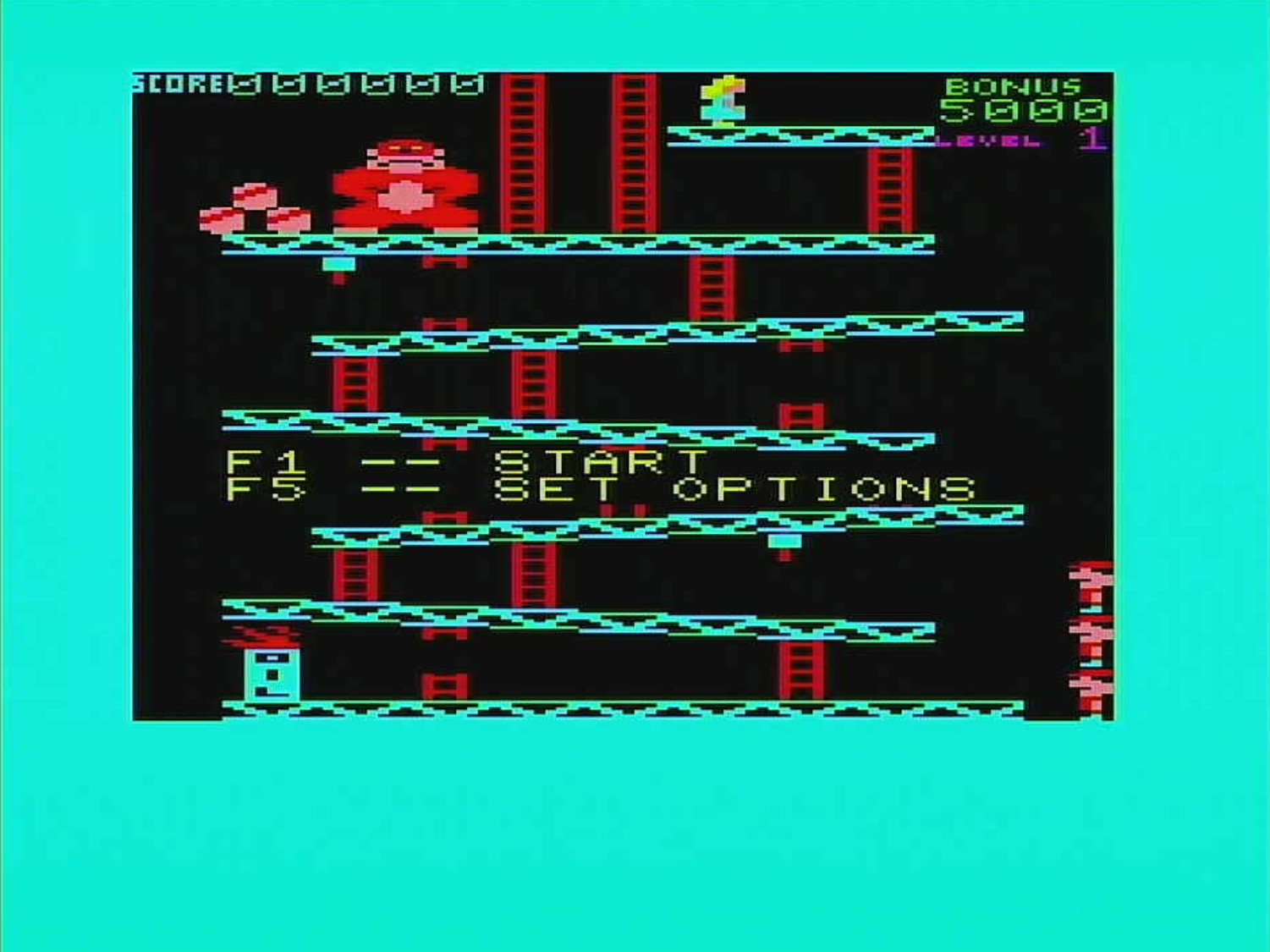
Donkey Kong after the S-Video mod
.
The previous pictures were captured with the VickyTwenty connected to the Frame Meister which was then connected to the MiraBox HDMI capture deviced. Both, composite video and S-Video screens were captured this way. The quality of the composite video looks slightly better on the TV than on the composite captures, but that were slight interferences due to long cables and a huge ground loop in the setup. The checker board problem, which some color combinations generate in composite is not matter of the described setup.
The previous pictures were captured with the VickyTwenty connected to the Frame Meister which was then connected to the MiraBox HDMI capture deviced. Both, composite video and S-Video screens were captured this way. The quality of the composite video looks slightly better on the TV than on the composite captures, but that were slight interferences due to long cables and a huge ground loop in the setup. The checker board problem, which some color combinations generate in composite is not matter of the described setup.
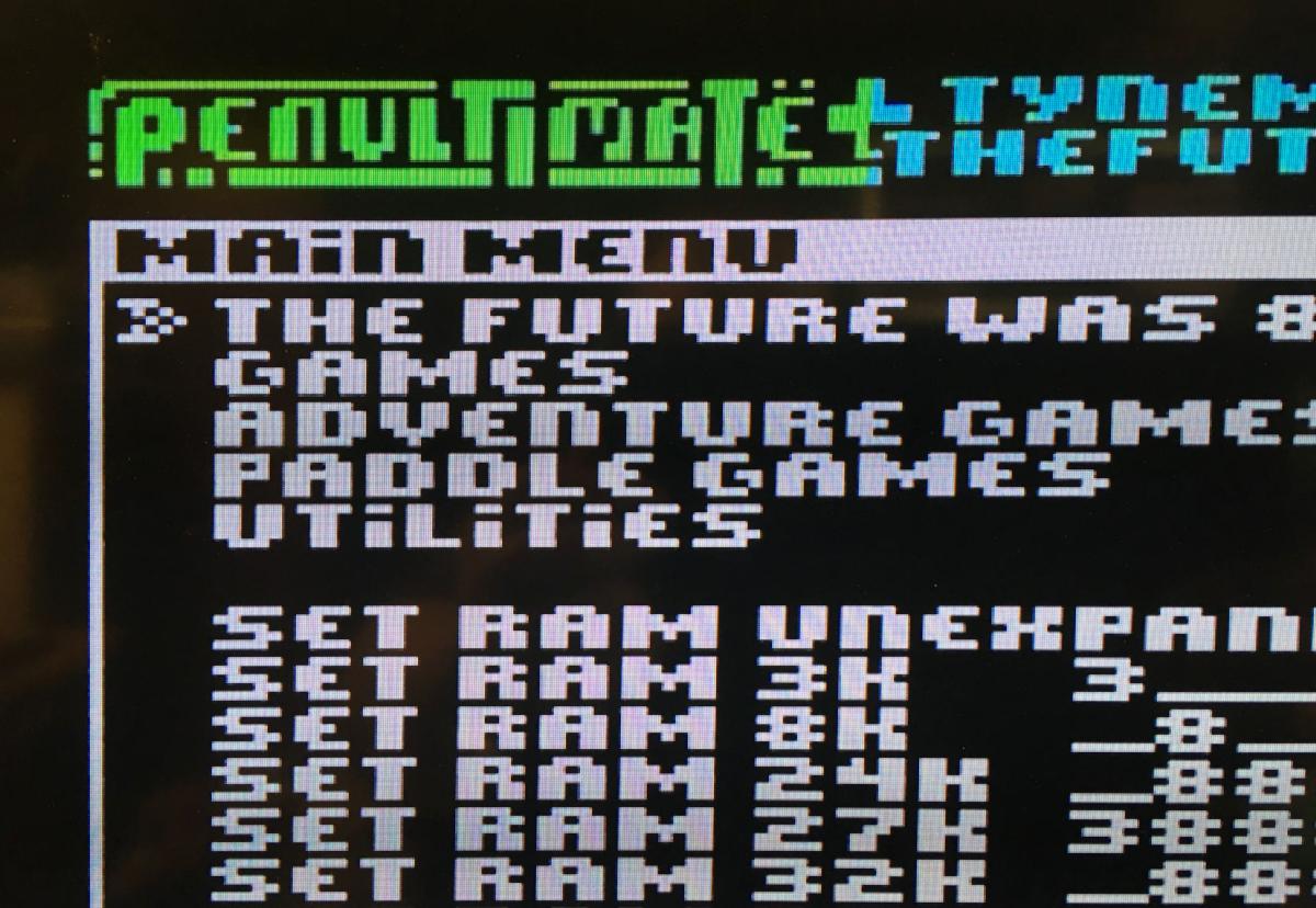
Photo takes from the TV screen after S-Video mod.