


C64 Kernal Adapter - Short Board
The short boards (ASSY 250469) only have one ROM that unites BASIC and the Kernal.
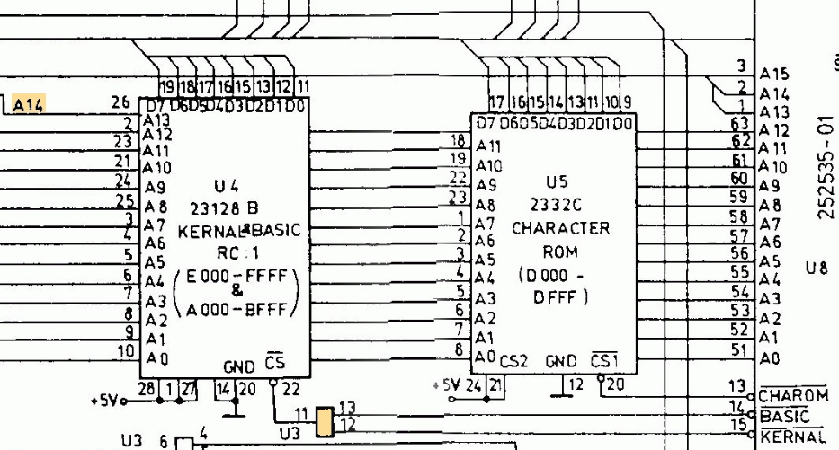
Excerpt from the schematics of ASSY250469
The BASIC resides in addresses A000 to BFFF. The Kernal in E000 to FFFF. The high nibble [A15...12] in binary looks like 1010bin to 1011bin for BASIC and 1110bin to 1111bin for teh Kernal. So it is obvious, that A14 discriminates between the BASIC and the Kernal.
The excerpt from the short board schematics shows the A14 is connected to A13 of the ROM. A13 now discriminates between the lower 8k (BASIC) and the higher 8k (Kernal). This is the reason, why an A14 address bit is connected to an A13 pin. Together with the AND gate U3, this does the trick of uniting BASIC and Kernal to one IC.
So, a simple kernal (and BASIC) adapter for a 64kB EPROM (27C512) can store four images for a 16kB BASIC and Kernal ROM with four copied of the same BASIC in the lower 8kB of the 16kB memory slot. But... it is not much more complicated to keep BASIC only once in the EPROM and have space for seven kernal images.
The trick is an AND gate (IC3) on the adapter, that diverts every access to the BASIC (pin 26/A13 = LOW) to 8k memory slot #0, where the BASIC is. All other ROM accesses will address the 8k memory slot, that is selected on a jumper.

Schematics of the Keral adapter for short boards (click to enlarge)
The Kernal adapter is providing 5V on one pin of the jumper. The purpose of this is powering a controller (like an Arduino) , that selects the kernals.
Rev. 2 provides an optional pin header (J1) with A5 and A8 for stereo SID applications.
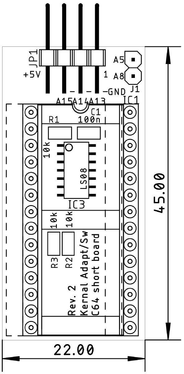
Dimensions
Please find the project documentation and rescources on github: https://github.com/svenpetersen1965/C64-Kernal-Adaptor-Switch-short-board-